 |
|||
|
|
|||
|
|
|||
| ||||||||||
|
|
 TM 9-2320-366-20-2
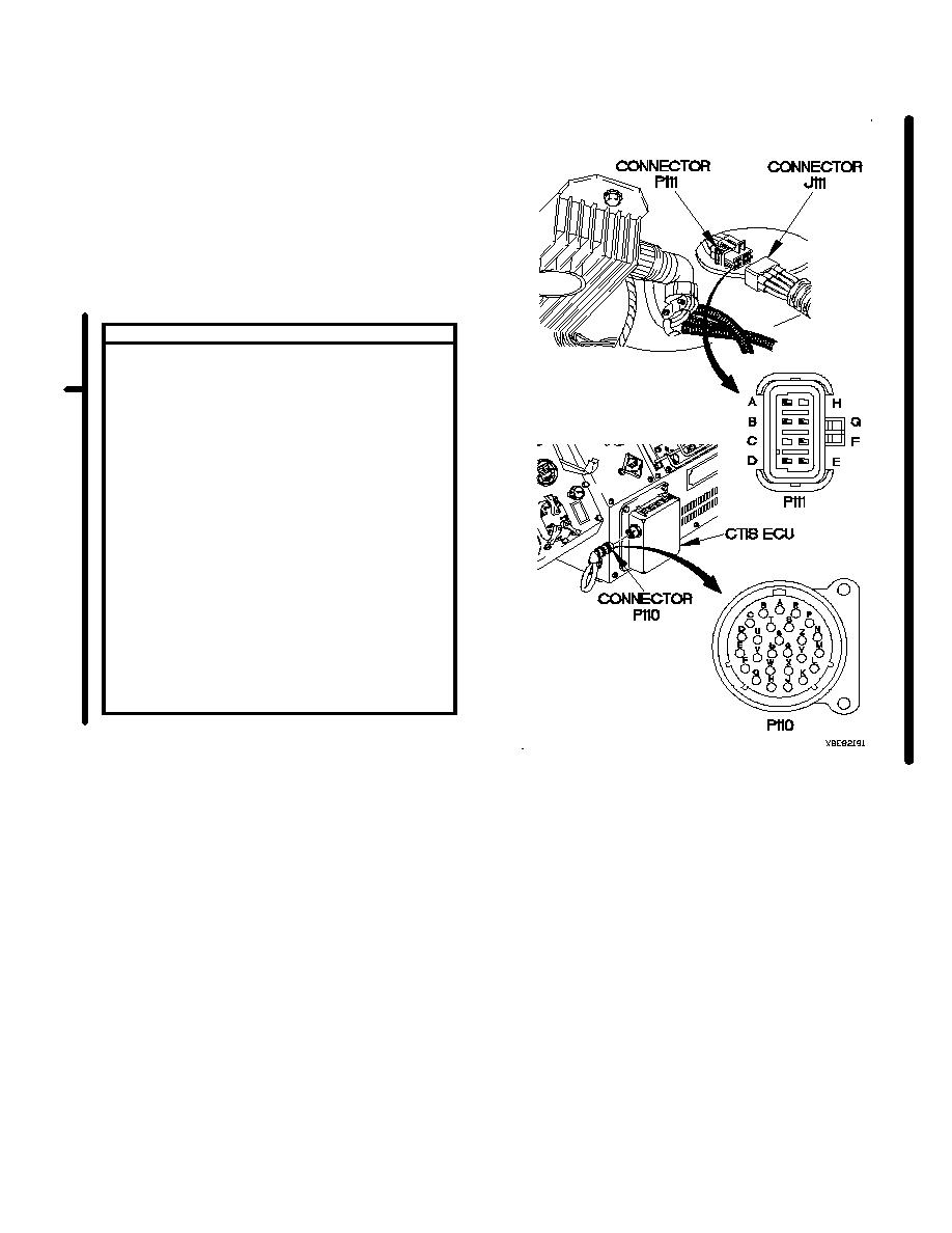
CONTINUITY TEST
(1) Remove kick panel (para 16-3).
(2) Disconnect connector J111 from connector
P111.
(3) Set multimeter to ohms.
(4) Connect positive (+) probe of multimeter to
connector P110 socket F.
(5) Connect negative (-) probe of multimeter to
connector P111 pin A and note reading on
multimeter.
(6) If continuity is not present replace CTIS
cable assembly (para 7-60).
(7) If continuity is present, repair wire 3031
from connector J111 socket A to terminal
board TB2 position 35 (para 2-45) or
replace WTEC II dashboard cable assembly
(para 7-10) or WTEC III dashboard cable
assembly (para 7-11).
(8) Connect connector J111 to connector
P111.
(9) Install kick panel (para 16-3).
(10) Connect connector P110 to CTIS ECU.
Change 2
2-959
|
|
Privacy Statement - Press Release - Copyright Information. - Contact Us |
