 |
|||
|
|
|||
|
|
|||
| ||||||||||
|
|
 TM 9-2320-366-20-2
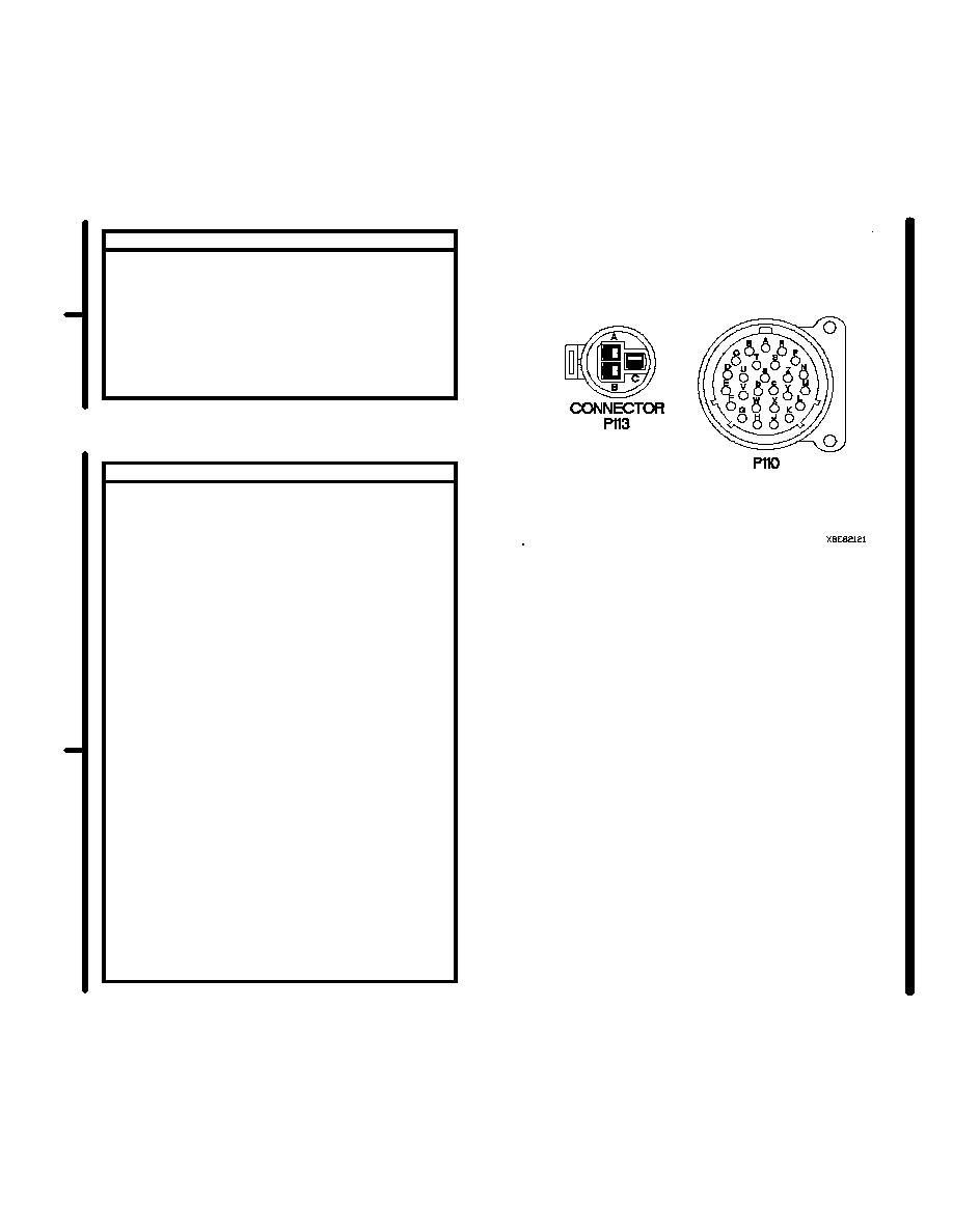
CONTINUITY TEST
(1) Set multimeter to ohms.
(2) Connect positive (+) probe of multimeter to
connector P110 socket j.
(3) Connect negative (-) probe of multimeter to
connector P113 socket A and note reading
on multimeter.
(4) If continuity is not present, replace CTIS
cable assembly (para 7-60).
CONTINUITY TEST
(1) Set multimeter to ohms.
(2) Connect positive (+) probe of multimeter to
connector P113 socket A.
(3) Connect negative (-) probe of multimeter to
known good ground and note reading on
multimeter.
(4) Connect negative (-) probe of multimeter to
all other sockets on connector P113 and
note reading on multimeter.
(5) Connect positive (+) probe of multimeter to
connector P113 socket B.
(6) Connect negative (-) probe of multimeter to
known good ground and note reading on
multimeter.
(7) Connect negative (-) probe of multimeter to
all other sockets on connector P113 and
note reading on multimeter.
(8) Connect positive (+) probe of multimeter to
connector P113 socket C.
(9) Connect negative (-) probe of multimeter to
known good ground and note reading on
multimeter.
(10) Connect negative (-) probe of multimeter to
all other sockets on connector P113 and note
reading on multimeter
(11) If continuity not present is steps 3, 4, 6, 7, 9,
and 10, go to step 20 of this fault.
(12) If continuity present is steps 3, 4, 6, 7, 9, or
10, replace CTIS cable assembly (para 7-60).
Change 2
2-958.11
|
|
Privacy Statement - Press Release - Copyright Information. - Contact Us |
