 |
|||
|
|
|||
|
|
|||
| ||||||||||
|
|
 TM 9-2320-366-20-1
TM
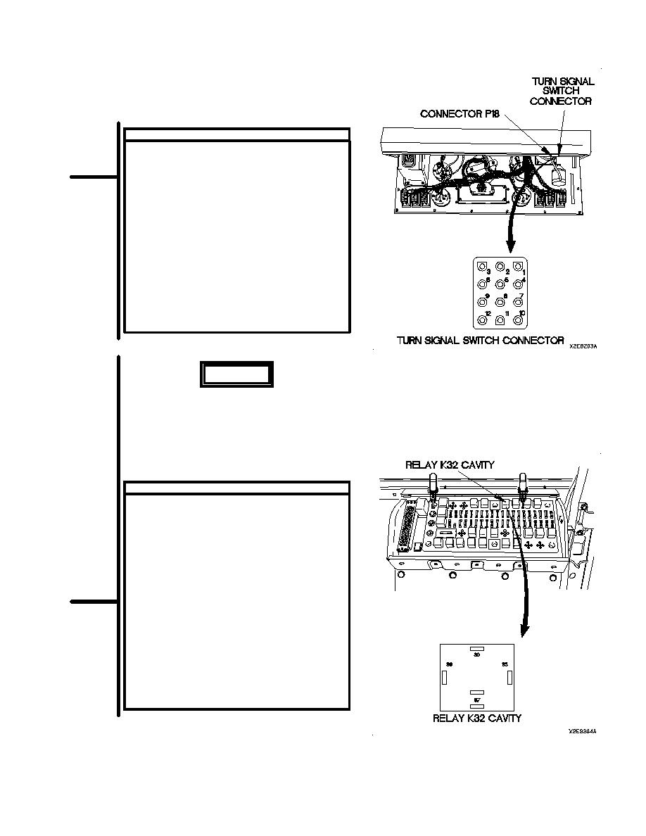
CONTINUITY TEST
(1)
Remove instrument panel assembly for access
(para 7-15).
(2)
Disconnect connector P18 from turn
signal switch connector.
(3)
Set multimeter to ohms.
(4)
Connect positive (+) probe of multimeter to
turn signal switch connector terminal 4.
(5)
Connect negative (-) probe of multimeter to
turn signal switch connector terminal 12.
(6)
Press horn button (TM 9-2320-366-10-1)
and note reading on multimeter.
(7)
If continuity is not present, replace turn
signal switch (para 7-26).
(8)
Connect connector P18 to turn signal
switch connector.
(9)
Install instrument panel assembly (para 7-15).
WARNING
Remove rings, bracelets, watches,
necklaces, and any other jewelry
before working around vehicle.
Jewelry can catch on equipment
and cause injury or short across
electrical circuit and cause severe
burns or electrical shock.
VOLTAGE TEST
(1)
Remove PDP cover (para 16-2).
(2)
Remove relay K32 from PDP.
(3)
Set multimeter to volts dc.
(4)
Connect positive (+) probe of multimeter to
PDP, terminal 86, where relay K32 was
removed.
(5)
Connect negative (-) probe of multimeter to
ground.
(6)
Position master power switch to on
(TM 9-2320-366-10-1).
(7)
Press horn button (TM 9-2320-366-10-1)
and note reading on multimeter.
(8)
If 24 vdc is not present, repair wire 25
(para 2-45) or WTEC II dashboard cable
assembly (para 7-10) or WTEC III dashboard
cable assembly (para 7-11).
(9)
Position master power switch to off
(TM 9-2320-366-10-1).
2-921
|
|
Privacy Statement - Press Release - Copyright Information. - Contact Us |
