 |
|||
|
|
|||
|
|
|||
| ||||||||||
|
|
 TM 9-2320-366-20-1
WARNING
Remove rings, bracelets, watches, necklaces,
and any other jewelry before working around
vehicle. Jewelry can catch on equipment and
cause injury or short across electrical circuits
and cause severe burns or electrical shock.
CAUTION
Use care when testing electrical connectors.
Do not damage connector pins or sockets
with multimeter probes. Failure to comply
may result in damage to equipment.
NOTE
Inspect connector pins/sockets for damage,
corrosion, and serviceability. Check that
connector pins are not pushed back and
are capable of making good contact.
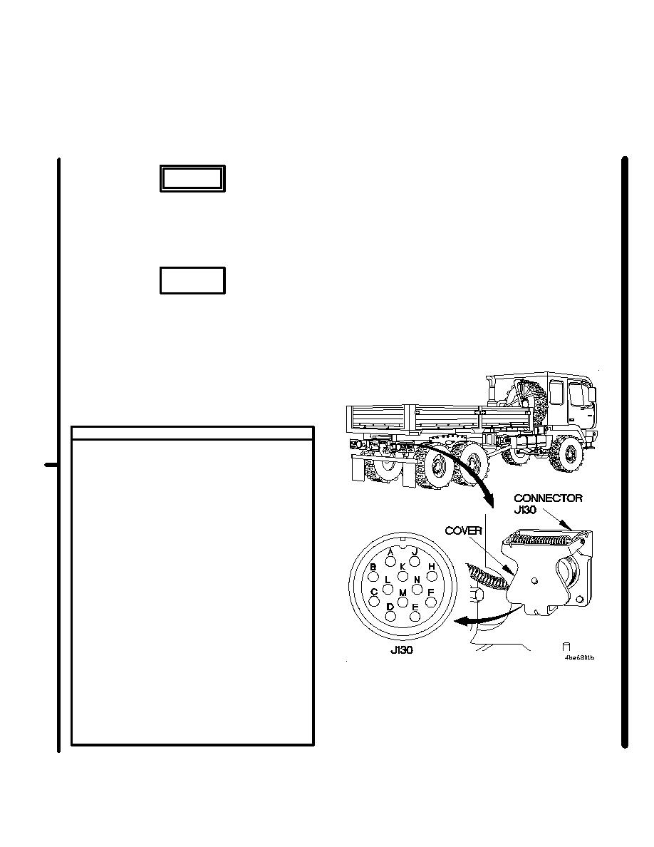
VOLTAGE TEST
(1) Lift cover on connector J130 intervehicular
24 VDC connector.
(2) Set multimeter to volts DC.
(3) Connect positive (+) probe of multimeter to
connector J130 socket A.
(4) Connect negative (-) probe of multimeter to
ground.
(5) Position main light switch to BO DRIVE
(TM 9-2320-366-10-1) and note reading
on multimeter.
(7) Connect positive (+) probe of multimeter to
connector J130 socket C.
(8) Connect negative (-) probe of multimeter to
ground and note reading on multimeter.
(9) Connect positive (+) probe of multimeter to
connector J130 socket H.
(10) Connect negative (-) probe of multimeter to
ground and note reading on multimeter.
(11) If 24 VDC is not present, go to step 2
of this fault.
(12) If 24 VDC is present, troubleshoot trailer
electrical system per trailer technical
manual.
(13) Position main light switch to OFF
(TM 9-2320-366-10-1).
Change 1
2-817
|
|
Privacy Statement - Press Release - Copyright Information. - Contact Us |
