 |
|||
|
|
|||
|
|
|||
| ||||||||||
|
|
 TM 9-2320-366-20-1
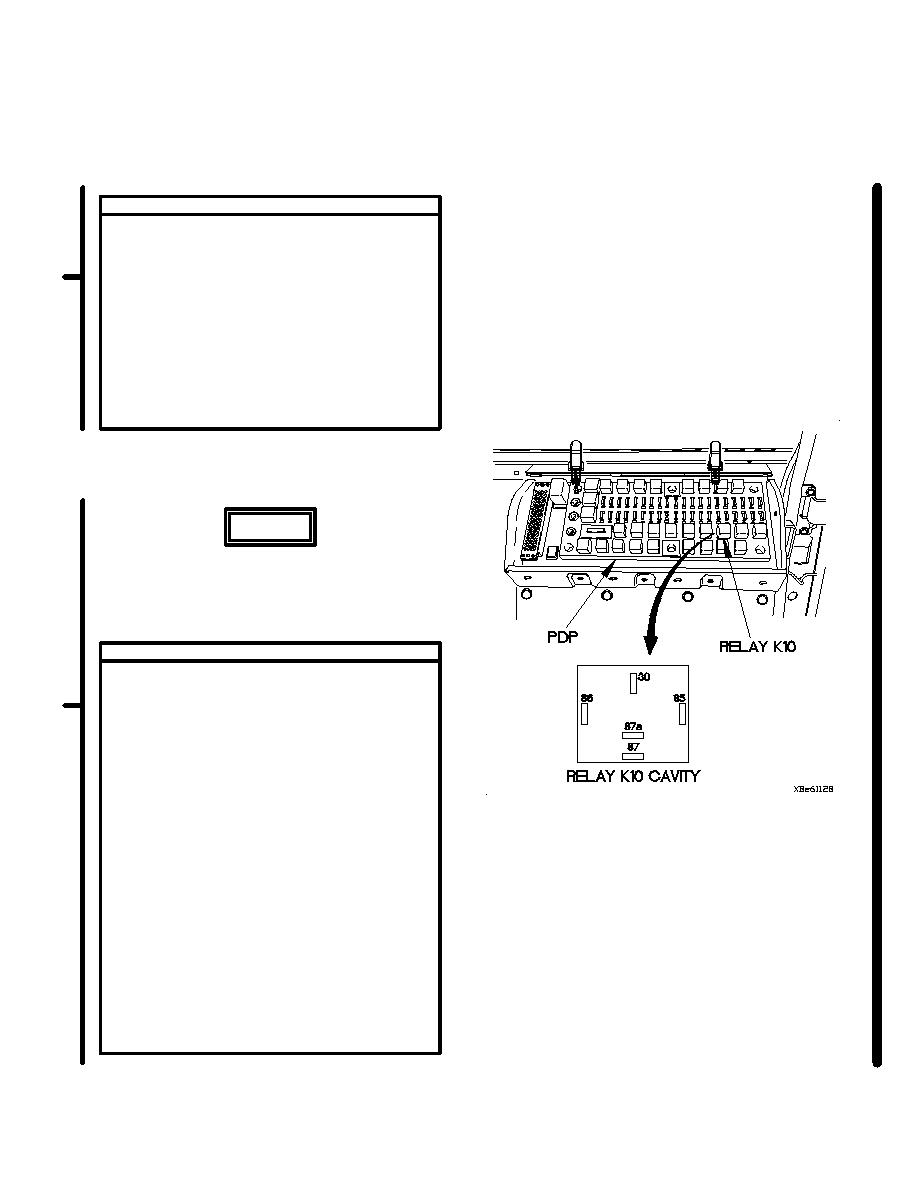
CONTINUITY TEST
(1) Set multimeter to ohms.
(2) Connect positive (+) probe of multimeter
to PDP, terminal 85, where relay K10
was removed.
(3) Connect negative (-) probe of multimeter
to ground and note reading on multimeter.
(4) If continuity is not present, repair wire 3046
from relay K10 terminal 85 to terminal board
TB2 position 60 (para 2-45) or replace
WTEC II dashboard cable assembly
(para 7-10) or WTEC III dashboard cable
assembly (para 7-11).
WARNING
Remove rings, bracelets, watches, necklaces,
and any other jewelry before working around
vehicle. Jewelry can catch on equipment and
cause injury or short across electrical circuits
and cause severe burns or electrical shock.
VOLTAGE TEST
(1) Set multimeter to volts DC.
(2) Connect positive (+) probe of multimeter
to PDP, terminal 87, where relay K10
was removed.
(3) Connect negative (-) probe of multimeter
to ground.
(4) Position master power switch to on
(TM 9-2320-366-10-1).
(5) Position main light switch to STOPLIGHT
(TM 9-2320-366-10-1).
(6) Apply brakes and note reading on
multimeter.
(7) If 12 VDC is not present, repair wire
1940 from relay K10 terminal 87 to
terminal board TB1 position 29
(para 2-45) or replace WTEC II
dashboard cable assembly (para 7-10)
or WTEC III dashsboard cable
assembly (para 7-11).
(8) Position main light switch to OFF
(TM 9-2320-366-10-1).
(9) Position master power switch to off
(TM 9-2320-366-10-1).
Change 1
2-757
|
|
Privacy Statement - Press Release - Copyright Information. - Contact Us |
