 |
|||
|
|
|||
|
|
|||
| ||||||||||
|
|
 TM 9-2320-366-20-1
TM
WARNING
Remove rings, bracelets, watches, necklaces,
and any other jewelry before working around
vehicle. Jewelry can catch on equipment and
cause injury or short across electrical circuit
and cause severe burns or electrical shock.
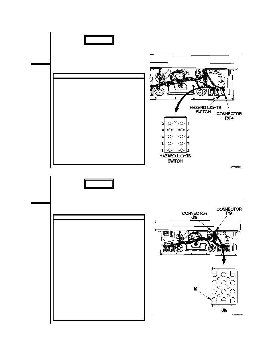
VOLTAGE TEST
(1)
Disconnect connector PX14 from hazard lights
switch.
(2)
Set multimeter to volts dc.
(3)
Connect positive (+) probe of multimeter to
connector PX14-7.
(4)
Connect negative (-) probe of multimeter to
ground.
(5)
Position main light switch to STOPLIGHT
(TM 9-2320-366-10-1) and note reading on
multimeter.
(6)
If 12 vdc is not present, repair wire 1514
(para 2-45) or replace WTEC II dashboard
cable assembly (para 7-10) or WTEC III
dashboard cable assembly (para 7-11).
(7)
Position main light switch to OFF
(TM 9-2320-366-10-1).
(8)
Connect connector PX14 to hazard light
switch.
WARNING
Remove rings, bracelets, watches, necklaces,
and any other jewelry before working around
vehicle. Jewelry can catch on equipment and
cause injury or short across electrical circuit
and cause severe burns or electrical shock.
VOLTAGE TEST
(1) Disconnect connector P19 from connector
J19.
(2) Set multimeter to volts dc.
(3) Connect positive (+) probe of multimeter to
connector J19-12.
(4) Connect negative (-) probe of multimeter to
ground.
(5) Position main light switch to STOPLIGHT
(TM 9-2320-366-10-1) and note reading on
multimeter.
(6) If voltage pulse is not present, repair wire
1644 (para 2-45) or replace WTEC II
dashboard cable assembly (para 7-10) or
WTEC III dashboard cable assembly
(para 7-11).
(7) If voltage pulse is present, replace turn
signal switch (para 7-26).
(8) Position main light switch to OFF
(TM 9-2320-366-10-1).
(9) Connect connector P19 to connector J19.
(10) Install instrument panel assembly (para 7-15).
2-729
|
|
Privacy Statement - Press Release - Copyright Information. - Contact Us |
