 |
|||
|
|
|||
|
|
|||
| ||||||||||
|
|
 TM 9-2320-366-20-1
CAUTION
Use care when testing electrical connectors.
Do not damage connector pins or sockets
with multimeter probes. Failure to comply
may result in damage to equipment.
NOTE
Inspect connector pins/sockets for damage,
corrosion, and serviceability. Check that
connector pins are not pushed back and
are capable of making good contact.
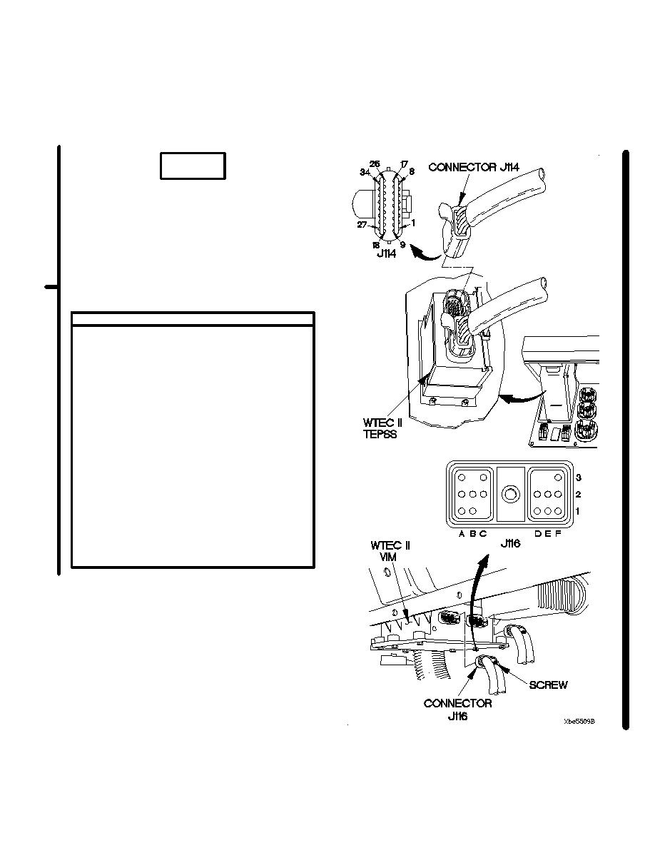
CONTINUITY TEST
(1) Remove instrument panel assembly for
access (para 7-15).
(2) Disconnect connector J114 from WTEC II
TEPSS.
(3) Loosen screw in connector J116.
(4) Disconnect connector J116 from WTEC II
VIM.
(5) Connect positive (+) probe of multimeter
to connector J116 socket F2.
(6) Connect negative (-) probe of multimeter to
connector J114 socket 13 and note reading
on multimeter.
(7) If continuity is not present, replace WTEC II
cab transmission harness (para 7-137).
(8) Connect connector J114 to WTEC II
TEPSS.
(9) Install instrument panel assembly (para
7-15).
(10) Connect connector J116 to WTEC II VIM.
(11) Tighten screw in connector J116.
Change 1
2-685
|
|
Privacy Statement - Press Release - Copyright Information. - Contact Us |
