 |
|||
|
|
|||
|
|
|||
| ||||||||||
|
|
 TM 9-2320-366-20-1
WARNING
Remove rings, bracelets, watches, necklaces,
and any other jewelry before working around
vehicle. Jewelry can catch on equipment and
cause injury or short across electrical circuits, or
cause severe burns or electrical shock.
CAUTION
Use care when testing electrical connectors not
to bend connector pins or damage connector
sockets with multimeter probes. Failure to
comply may result in damage to equipment.
NOTE
Inspect connector pins/sockets for damage,
corrosion, and serviceability. Check that
connector pins are not pushed back and
are capable of making good contact.
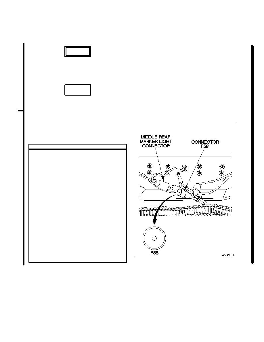
VOLTAGE TEST
(1) Disconnect middle rear marker light
connector from connector P56.
(2) Set multimeter to volts DC.
(3) Connect positive (+) probe of multimeter
to connector P56.
(4) Connect negative (-) probe of multimeter to
ground.
(5) Position main light switch to SER DRIVE
(TM 9-2320-366-10-1) and note reading
on multimeter.
(6) Position main light switch to OFF
(TM 9-2320-366-10-1).
(7) If 12 VDC is not present, repair wire 489
from connector P56 to splice E27
(para 2-45) and go to step 4 of this fault if
required or replace M1088 rear lights cable
assembly (para 7-104) and go to step 1 of
this fault.
(8) If 12 VDC is present, replace middle rear
marker light (para 7-38) and go to step 4
of this fault if required.
(9) Connect middle rear marker light connector
to connector P58.
Change 1
|
|
Privacy Statement - Press Release - Copyright Information. - Contact Us |
