 |
|||
|
|
|||
|
|
|||
| ||||||||||
|
|
 TM 9-2320-366-20-1
CAUTION
Use care when testing electrical connectors.
Do not damage connector pins or sockets
with multimeter probes. Failure to comply
may result in damage to equipment.
NOTE
Inspect connector pins/sockets for damage,
corrosion, and serviceability. Check that
connector pins are not pushed back and
are capable of making good contact.
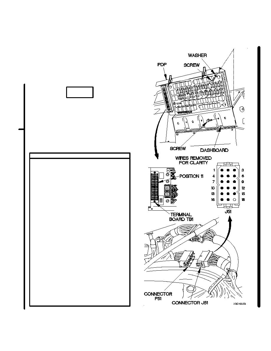
CONTINUITY TEST
(1) Disconnect batteries (para 7-57).
(2) Remove PDP cover (para 16-2).
(3) Remove three screws and washers from
PDP.
(4) Remove three screws from PDP.
(5) Lift PDP outward to gain access.
(6) Disconnect connector P51 from connector
J51.
(7) Set multimeter to ohms.
(8) Connect positive (+) probe of multimeter
to connector J51 pin 7.
(9) Connect negative (-) probe of multimeter
to terminal board TB1 position 11 and note
reading on multimeter.
(10) If continuity is not present, repair wire 489
from connector J51 pin 7 to terminal board
TB1 position 11 (para 2-45) or replace
WTEC II dashboard cable assembly
(para 7-10) or WTEC III dashboard cable
assembly (para 7-11).
(11) If continuity is present, repair wire 489
from connector P51 socket 7 to splice
E15 (para 2-45) or replace rear lights
cable assembly (para 7-84).
(12) Connect connector J51 to connector P51.
(13) Install PDP on dashboard with three
screws.
(14) Install three washers and screws in PDP.
(15) Install PDP cover (para 16-2).
(16) Connect batteries (para 7-57).
Change 1
2-600.11
|
|
Privacy Statement - Press Release - Copyright Information. - Contact Us |
