 |
|||
|
|
|||
|
|
|||
| ||||||||||
|
|
 TM 9-2320-366-20-1
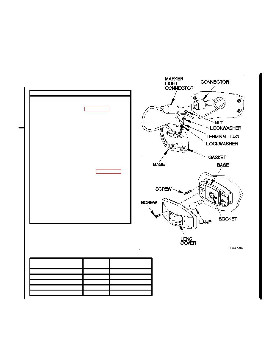
CONTINUITY TEST
(1) Set multimeter to ohms.
(2) Connect positive (+) probe of multimeter to
terminal lug (Refer to Table 2-11.2. Cab
Clearance and Marker Light
Terminal Lugs).
(3) Connect negative (-) probe of multimeter to
to ground and note reading on multimeter.
(4) If continuity is not present, repair wire 3097
(para 2-45) or replace cab clearance and
marker lights cable assembly (para 7-66)
or M1093/M1094 cab clearance and marker
lights upper cable assembly (para 7-63).
(5) If continuity is present, replace marker light
assembly (para 7-38).
(6) Install gasket on marker light base.
(7) Connect connector (Refer to Table 2-11.2.
Cab Clearance and Marker Light
Connectors) to marker light connector.
(8) Install lockwasher, terminal lug (Refer to
Table 2-11.2. Cab Clearance and
Marker Light Terminal Lugs),
lockwasher, and nut on back of base.
(9) Install marker light base on vehicle with four
screws.
(10) Install marker light lamp in socket.
(11) Install lens cover on base with two screws.
Table 2-11.2. Cab Clearance and Marker Light Terminal Lugs
Light
Terminal Lug
Wire Segment
RH Cab Top Marker Light
TL3
TL3 to splice E24
RH Cab Top ID Light
TL4
TL4 to splice E24
Middle Cab Top ID Light
TL8
TL8 to splice E24
LH Cab Top ID Light
TL22
TL22 to splice E24
LH Cab Top Marker Light
TL27
TL27 to splice E24
Change 1
|
|
Privacy Statement - Press Release - Copyright Information. - Contact Us |
