 |
|||
|
|
|||
|
|
|||
| ||||||||||
|
|
 TM 9-2320-366-20-1
VOLTAGE TEST (CONT)
WARNING
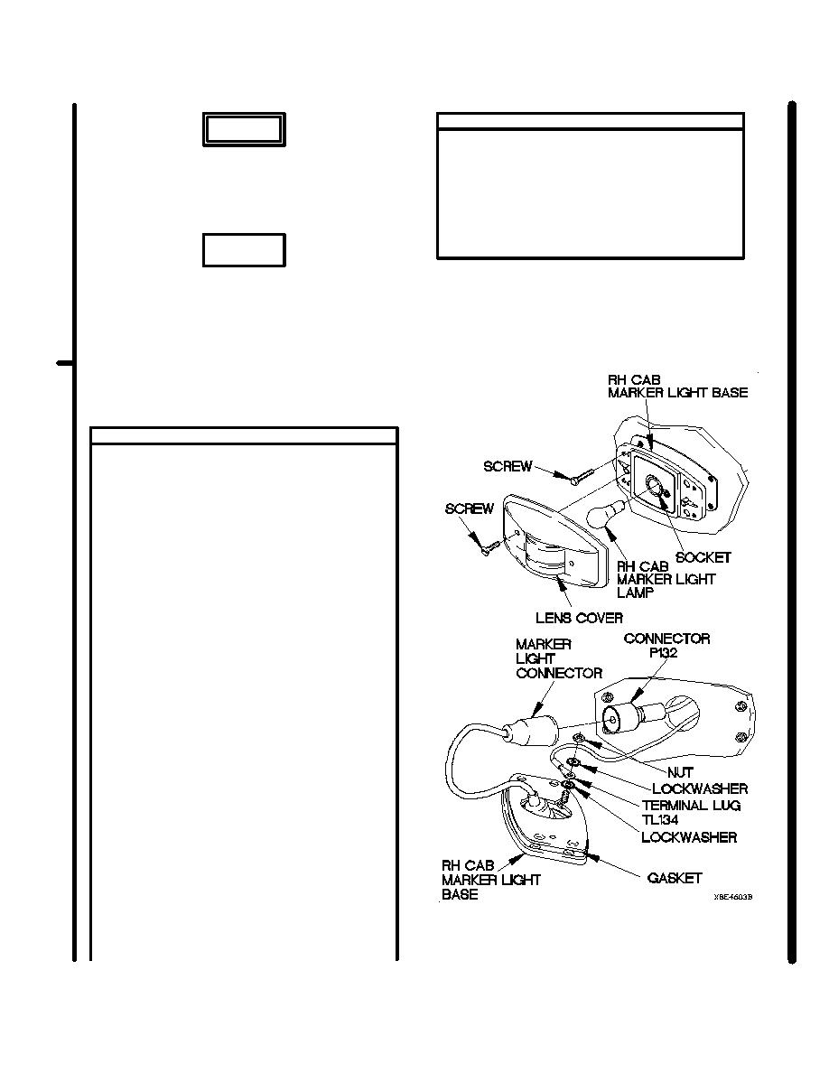
(14) Install lockwasher, terminal lug TL134,
Remove rings, bracelets, watches, necklaces,
lockwasher, and nut on back of RH cab
and any other jewelry before working around
marker light base.
vehicle. Jewelry can catch on equipment and
(15) Install RH cab marker light base on vehicle
cause injury or short across electrical circuits
with four screws.
and cause severe burns or electrical shock.
(16) Install RH cab marker light lamp in socket.
(17) Install lens cover on base with two
screws.
CAUTION
Use care when testing electrical connectors.
Do not damage connector pins or sockets
with multimeter probes. Failure to comply
may result in damage to equipment.
NOTE
Inspect connector pins/sockets for damage,
corrosion, and serviceability. Check that
connector pins are not pushed back and
are capable of making good contact.
VOLTAGE TEST
(1) Remove four screws from RH cab marker
light base.
NOTE
Do not let wires slip through hole into cab
structure. If wires slip into cab structure,
vehicle will need further disassembly to
retrieve wires.
(2) Remove nut, lockwasher, terminal lug TL134,
and lockwasher from RH cab marker light
base. Discard lockwashers.
(3) Extend base and disconnect connector P132
from marker light connector.
(4) Remove gasket from RH cab marker light
base. Discard gasket.
(5) Set multimeter to volts DC.
(6) Connect positive (+) probe of multimeter
to connector P132 socket.
(7) Connect negative (-) probe of multimeter
to ground.
(8) Position main light switch to SER DRIVE
(TM 9-2320-366-10-1) and note reading on
multimeter.
(9) If 12 VDC is not present, repair wire 1947
from connector P132 socket to splice E22
(para 2-45) or replace RH door and cab
marker lights cable assembly (para 7-64).
(10) If 12 VDC is present, replace RH cab marker
light (para 7-38).
(11) Position main light switch to OFF
(TM 9-2320-366-10-1).
(12) Install gasket on RH cab marker light base.
(13) Connect marker light connector to connector
P132.
Change 1
|
|
Privacy Statement - Press Release - Copyright Information. - Contact Us |
