 |
|||
|
|
|||
|
|
|||
| ||||||||||
|
|
 TM 9-2320-366-20-1
NOTE
Inspect connector pins/sockets for damage,
corrosion, and serviceability. Check that
connector pins are not pushed back and
are capable of making good contact.
CONTINUITY TEST
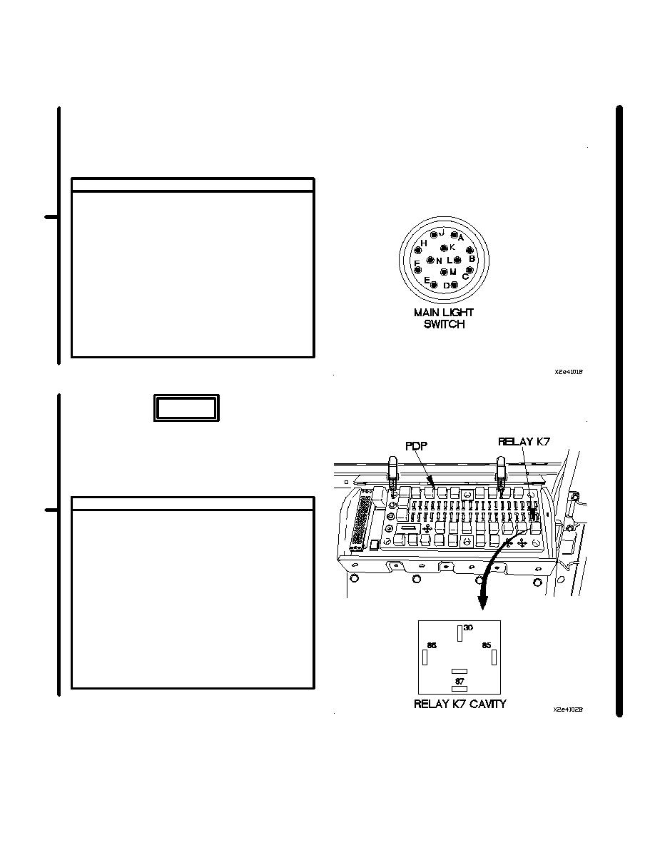
(1) Remove main light switch (para 7-17).
(2) Position main light switch to SER DRIVE
(TM 9-2320-366-10-1).
(3) Set multimeter to ohms.
(4) Connect positive (+) probe of multimeter
to main light switch terminal M.
(5) Connect negative (-) probe of multimeter
to main light switch terminal F and note
reading on multimeter.
(6) If continuity is not present replace main
light switch (para 7-17).
(7) Position main light switch to OFF
(TM 9-2320-366-10-1).
(8) Install main light switch (para 7-17).
WARNING
Remove rings, bracelets, watches, necklaces,
and any other jewelry before working around
vehicle. Jewelry can catch on equipment and
cause injury or short across electrical circuits
and cause severe burns or electrical shock.
VOLTAGE TEST
(1)
Remove PDP cover (para 16-2).
(2)
Remove relay K7 form PDP.
(3)
Set multimeter to volts DC.
(4)
Connect positive (+) probe of multimeter
to PDP terminal 86, where relay K7 was
removed.
(5)
Connect negative (-) probe of multimeter
to ground.
(6)
Position main light switch to SER DRIVE
(TM 9-2320-366-10-1) and note reading on
multimeter.
(7)
If 12 VDC is not present, go to step 9 of
this fault.
(8)
Position main light switch to OFF
(TM 9-2320-366-10-1).
Change 1
2-535
|
|
Privacy Statement - Press Release - Copyright Information. - Contact Us |
