 |
|||
|
|
|||
|
|
|||
| ||||||||||
|
|
 TM 9-2320-366-20-1
TM
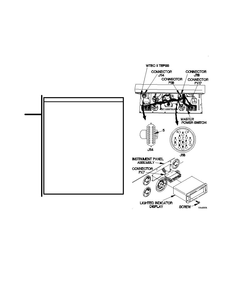
CONTINUITY TEST
(1)
Disconnect connector J114 (bottom
connector) from WTEC II TEPSS.
(2)
Set multimeter to ohms.
(3)
Connect positive (+) probe of multimeter to
connector J114-5.
(4)
Connect negative (-) probe of multimeter to
connector J118-1 and note reading on
multimeter.
(5)
If continuity is not present, repair wire 105
(para 2-45) or replace WTEC II cab transmission
harness (para 7-137).
(6)
If continuity is present, replace WTEC II TEPSS
(para 8-2).
(7)
Connect connector J114 to WTEC II TEPSS.
(8)
Connect connector J118 to connector P118.
(9)
Install instrument panel assembly (para 7-15).
(10)
Connect lighted indicator display to connector
PX7.
(11)
Position lighted indicator display in instrument
panel assembly with four screws.
(12)
Tighten four screws to 6-10 lb-in. (1 Nm).
(13)
Connect batteries (para 7-57).
2-503
|
|
Privacy Statement - Press Release - Copyright Information. - Contact Us |
