 |
|||
|
|
|||
|
|
|||
| ||||||||||
|
|
 TM 9-2320-366-20-1
TM
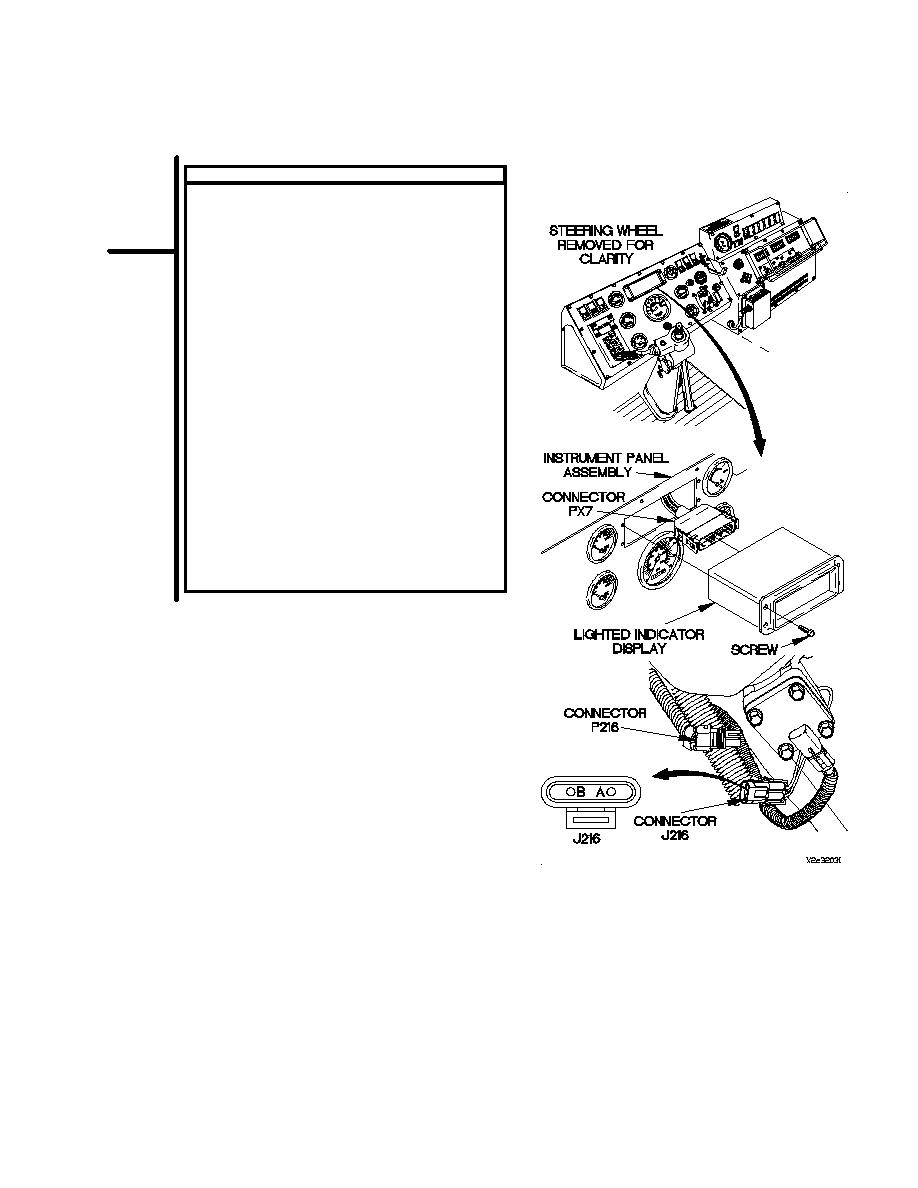
CONTINUITY TEST
(1)
Connect lighted indicator display to connector
PX7.
(2)
Position lighted indicator display in instrument
panel assembly with four screws.
(3)
Tighten four screws to 6-10 lb-in. (1 Nm).
(4)
Connect batteries (para 7-57).
(5)
Set multimeter to ohms.
(6)
Connect positive (+) probe of multimeter to
connector J216-B.
(7)
Connect negative (-) probe of multimeter to
connector J216-A.
(8)
Start engine (TM 9-2320-366-10-1).
(9)
Position PTO switch to on
(TM 9-2320-366-10-1) and note reading on
multimeter.
(10)
If continuity is not present, notify DS
Maintenance.
(11)
If continuity is present, repair wire 3025
(para 2-45) or replace PTO cable assembly
(para 7-127).
(12)
Position PTO switch to off
(TM 9-2320-366-10-1).
(13)
Shut down engine (TM 9-2320-366-10-1).
(14)
Connect connector P216 to connector J216.
2-475
|
|
Privacy Statement - Press Release - Copyright Information. - Contact Us |
