 |
|||
|
|
|||
|
|
|||
| ||||||||||
|
|
 TM 9-2320-366-20-1
TM
WARNING
Remove rings, bracelets, watches,
necklaces, and any other jewelry
before working around vehicle.
Jewelry can catch on equipment
and cause injury or short across
electrical circuit and cause severe
burns or electrical shock.
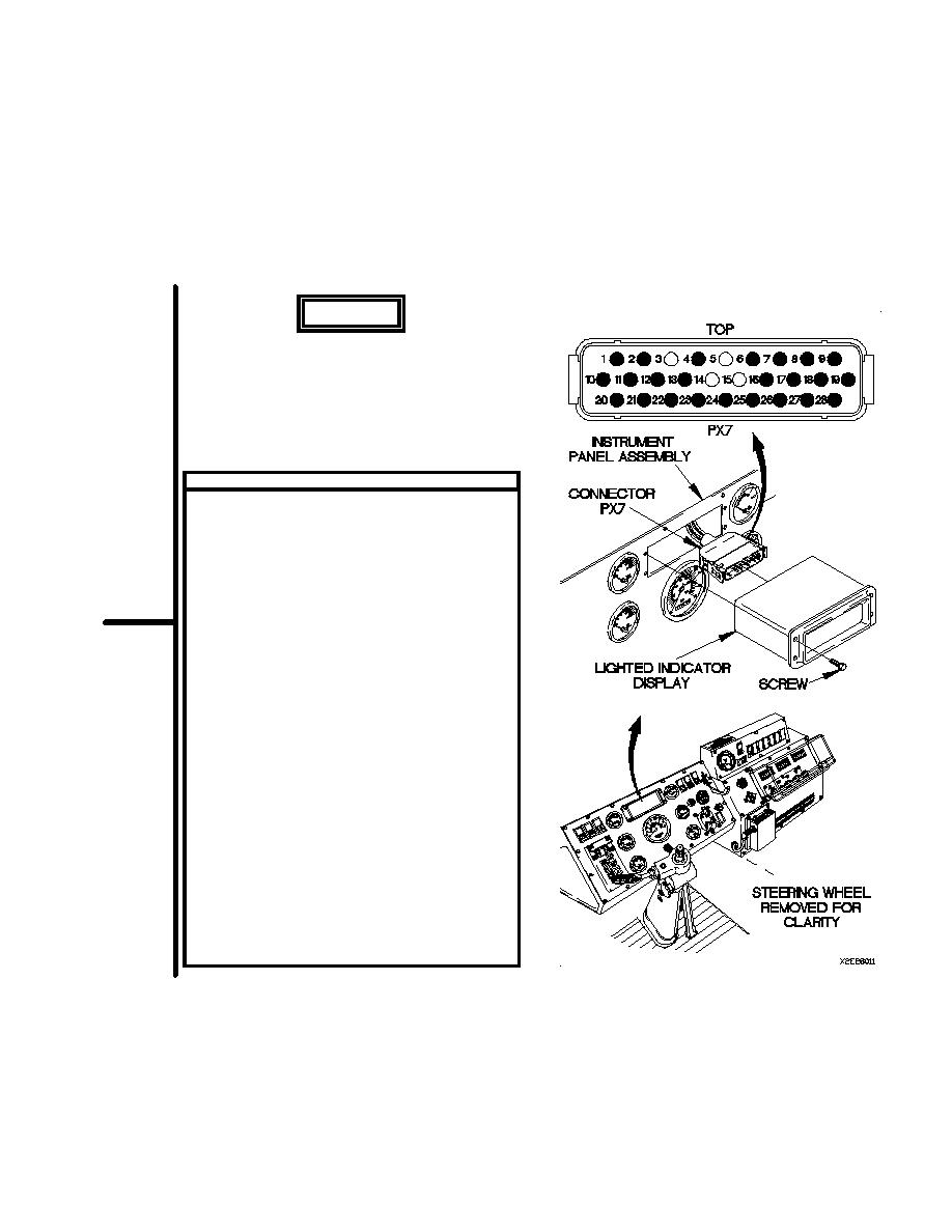
VOLTAGE TEST
(1)
Remove four screws from lighted indicator
display.
(2)
Remove lighted indicator display from
instrument panel assembly.
(3)
Disconnect connector PX7 from lighted
indicator display.
(4)
Connect batteries (para 7-57).
(5)
Set multimeter to volts dc.
(6)
Connect positive (+) probe of multimeter to
connector PX7-4.
(7)
Connect negative (-) probe of multimeter to
ground.
(8)
Position master power switch to on
(TM 9-2320-366-10-1).
(9)
Position main light switch to SER DRIVE
(TM 9-2320-366-10-1).
(10)
Position right signal to right turn signal position
(TM 9-2320-366-10-1) and note reading on
multimeter.
(11)
If voltage pulse is not present, go to step 3
of this fault.
(12)
Position master power switch to off
(TM 9-2320-366-10-1).
(13)
Position main light switch to OFF
(TM 9-2320-366-10-1).
(14)
Position turn signal control to middle position
(TM 9-2320-366-10-1).
2-443
|
|
Privacy Statement - Press Release - Copyright Information. - Contact Us |
