 |
|||
|
|
|||
|
|
|||
| ||||||||||
|
|
 TM 9-2320-366-20-1
TM
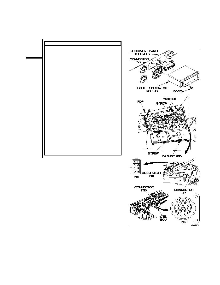
CONTINUITY TEST
(1)
Remove PDP cover (para 16-2).
(2)
Remove three screws and washers from PDP.
(3)
Remove three screws from PDP.
(4)
Lift PDP outward to gain access.
(5)
Disconnect connector P111 from connector
J111.
(6)
Set multimeter to ohms.
(7)
Connect positive (+) probe of multimeter to
connector P110-S.
(8)
Connect negative (-) probe of multimeter to
connector P111-G and note reading on
multimeter.
(9)
If continuity is not present, replace CTIS cable
assembly (para 7-60).
(10)
If continuity is present, repair wire 1911
(para 2-45) or replace WTEC II dashboard cable
assembly (para 7-10) or WTEC III dashboard
cable assembly (para 7-11).
(11)
Connect connector P111 to connector J111.
(12)
Install PDP on dashboard with three screws.
(13)
Install three washers and screws in PDP.
(14)
Install PDP cover (para 16-2).
(15)
Connect lighted indicator display to connector
PX7.
(16)
Position lighted indicator display in instrument
panel assembly with four screws.
(17)
Tighten four screws to 6-10 lb-in. (1 Nm).
2-431
|
|
Privacy Statement - Press Release - Copyright Information. - Contact Us |
