 |
|||
|
|
|||
|
|
|||
| ||||||||||
|
|
 TM 9-2320-366-20-1
WARNING
Remove rings, bracelets, watches, necklaces,
and any other jewelry before working around
vehicle. Jewelry can catch on equipment and
cause injury or short across electrical circuits
and cause severe burns or electrical shock.
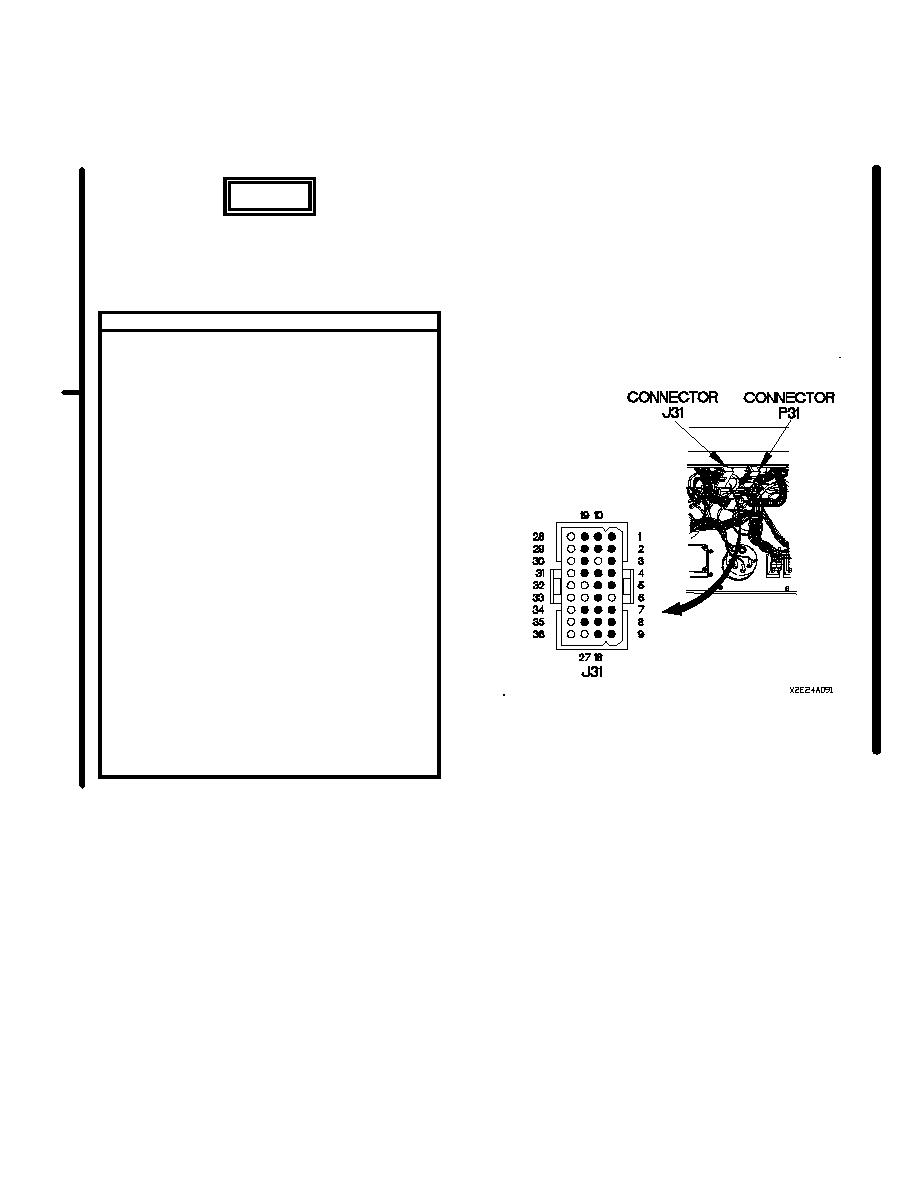
VOLTAGE TEST
(1) Disconnect batteries (para 7-57).
(2) Disconnect connector J31 from connector
P31.
(3) Connect batteries (para 7-57).
(4) Set multimeter to volts DC.
(5) Connect positive (+) probe of multimeter to
connector J31 pin 22.
(6) Connect negative (-) probe of multimeter to
known good ground.
(7) Position master power switch to on and
note reading on multimeter.
(8) Is 24 VDC is not present, repair wire 35
from connector PX7 pin 12 to connector
J31 pin 22 (para 2-45) or replace WTEC II
dashboard cable assembly (para 7-10) or
replace WTEC III dashboard cable assembly
(para 7-11).
(9) If 24 VDC is present, repair wire 35 from
connector P31 socket 22 to connector P37
pin 2 (para 2-45) or replace engine control
cable assembly (para 7-80).
(10) Position master power switch to off
(TM 9-2320-366-10-1).
(11) Disconnect batteries (para 7-57).
(12) Connect connect P31 to connector J31.
(13) Install instrument panel assembly (para 7-15).
(14) Connect batteries (para 7-57).
Change 2
2-418.15
|
|
Privacy Statement - Press Release - Copyright Information. - Contact Us |
