 |
|||
|
|
|||
|
|
|||
| ||||||||||
|
|
 TM 9-2320-366-20-1
WARNING
Remove rings, bracelets, watches, necklaces,
and any other jewelry before working around
vehicle. Jewelry can catch on equipment and
cause injury or short across electrical circuits
and cause severe burns or electrical shock.
CAUTION
Use care when testing electrical connectors.
Do not damage connector pins or sockets
with multimeter probes. Failure to comply
may result in damage to equipment.
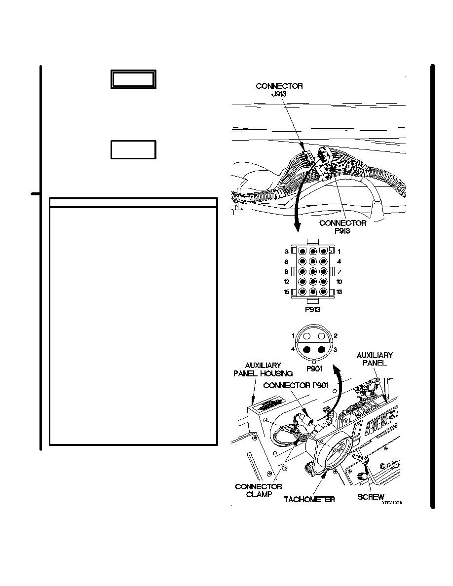
VOLTAGE TEST
(1) Remove personnel heater for access (para
18-9).
(2) Set multimeter to volts DC.
(3) Connect positive (+) probe of multimeter
to connector J913 socket 11.
(4) Connect negative (-) probe of multimeter to
ground.
(5) Position main light switch main selector
lever to SER DRIVE (TM 9-2320-366-
10-1).
(6) Position main light switch auxiliary lever
to PNL BRT (TM 9-2320-366-10-1) and
note reading on multimeter.
(7) If 12 VDC is not present, repair wire 1908
from connector J913 socket 11 to
connector PX14A socket 1 (para 2-45) or
replace WTEC II dashboard cable assembly
(para 7-10) or WTEC III dashboard cable
assembly (para 7-11).
(8) If 12 VDC is present, repair wire 1908
from connector P913 pin 11 to connector
P901 socket 2 (para 2-45) or replace
auxiliary panel cable assembly (para 7-58).
(9) Position main light switch auxiliary lever
to OFF (TM 9-2320-366-10-1).
(10) Position main light switch main selector
lever to OFF (TM 9-2320-366-10-1).
(11) Install personnel heater assembly (para
18-9).
Change 1
2-402.3
|
|
Privacy Statement - Press Release - Copyright Information. - Contact Us |
