 |
|||
|
|
|||
|
|
|||
| ||||||||||
|
|
 TM 9-2320-366-20-1
CAUTION
Use care when testing electrical connectors.
Do not damage connector pins or sockets
with multimeter probes. Failure to comply
may result in damage to equipment.
NOTE
Inspect connector pins/sockets for damage,
corrosion, and serviceability. Check that
connector pins are not pushed back and
are capable of making good contact.
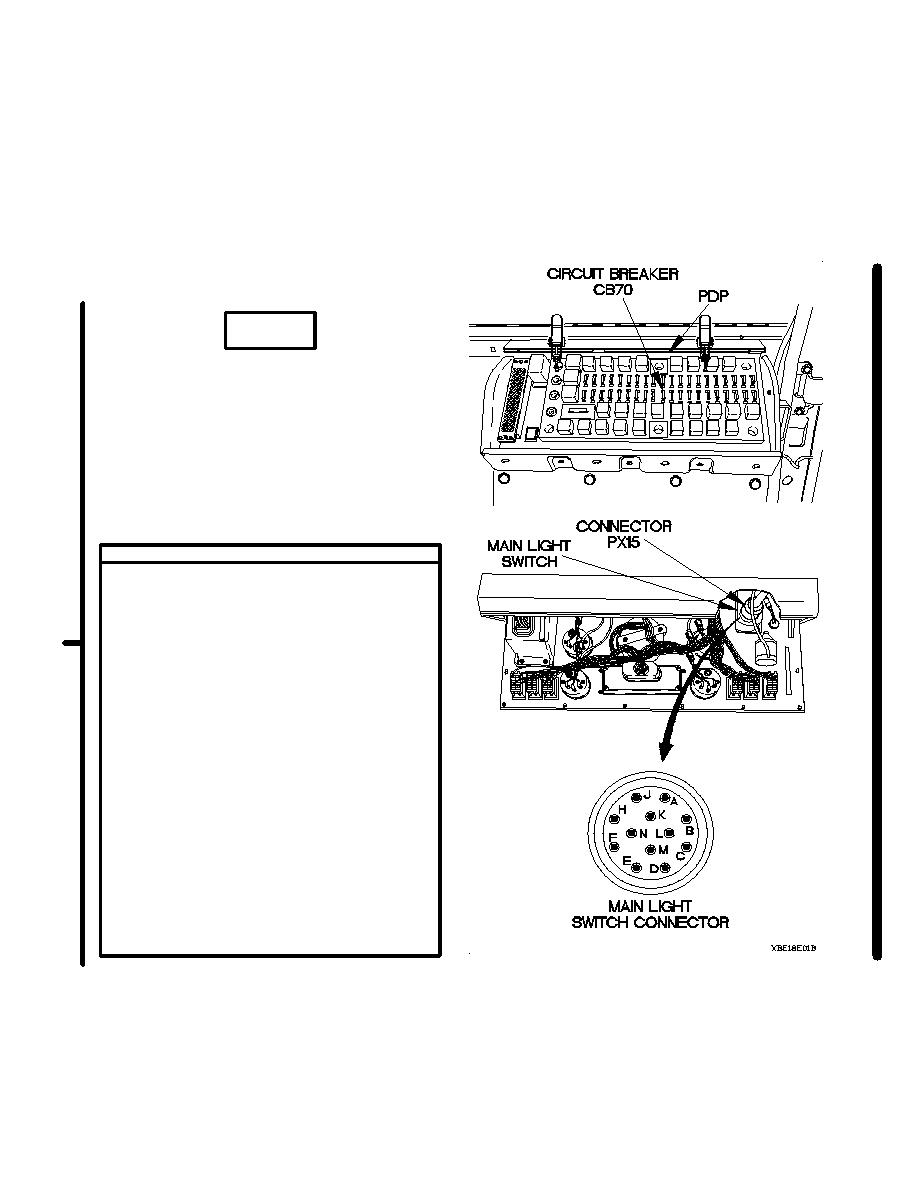
CONTINUITY TEST
(1) Remove PDP cover (TM 9-2320-366-10-2).
(2) Remove circuit breaker CB70 from PDP.
(3) Remove instrument panel assembly for
access (para 7-15).
(4) Disconnect connector PX15 from main
light switch connector.
(5) Position main light switch main selector
lever to SER DRIVE (TM 9-2320-366-
10-1).
(6) Position main light switch auxiliary selector
lever to PNL BRT (TM 9-2320-366-10-1).
(7) Set multimeter to ohms.
(8) Connect positive (+) probe of multimeter
to main light switch connector pin F.
(9) Connect negative (-) probe of multimeter to
main light switch connector pin B and note
reading on multimeter.
(10) If continuity is not present, replace main
light switch (para 7-17).
(11) Position main light switch auxiliary lever to
OFF (TM 9-2320-366-10-1).
(12) Position main light switch main selector
lever to OFF (TM 9-2320-366-10-1).
Change 1
2-390.19
|
|
Privacy Statement - Press Release - Copyright Information. - Contact Us |
