 |
|||
|
|
|||
|
|
|||
| ||||||||||
|
|
 TM 9-2320-366-20-1
CAUTION
Use care when testing electrical connectors.
Do not damage connector pins or sockets
with multimeter probes. Failure to comply
may result in damage to equipment.
NOTE
Inspect connector pins/sockets for damage,
corrosion, and serviceability. Check that
connector pins are not pushed back and
are capable of making good contact.
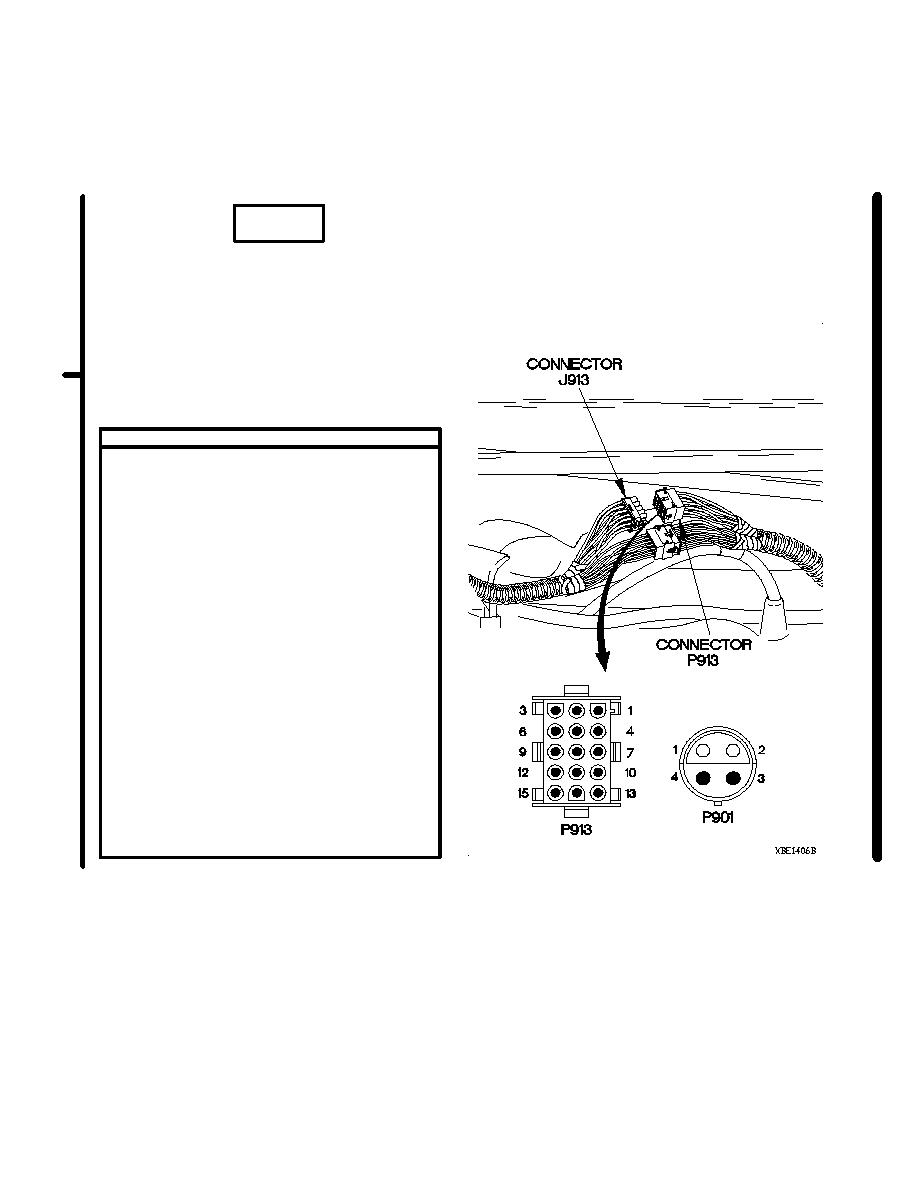
CONTINUITY TEST
(1) Remove personnel heater assembly for
access (para 18-9).
(2) Disconnect connector P913 from
connector J913.
(3) Set multimeter to ohms.
(4) Connect positive (+) probe of multimeter
to connector P901 pin 4.
(5) Connect negative (-) probe of multimeter
to connector P913 pin 12 and note reading
on multimeter.
(6) If continuity is not present, repair wire 1550
from connector P901 pin 4 to connector
P913 pin 12 (para 2-45) or replace auxiliary
panel cable assembly (para 7-58).
(7) If continuity is present, repair wire 1550
from connector J913 socket 12 to
connector PX26 socket 1 (para 2-45) or
replace WTEC II dashboard cable assembly
(para 7-10) or WTEC III dashboard cable
assembly (para 7-11).
(8) Connect connector P913 to connector
J913.
(9) Install personnel heater assembly (para
18-9).
Change 1
2-366.5
|
|
Privacy Statement - Press Release - Copyright Information. - Contact Us |
