 |
|||
|
|
|||
|
Page Title:
CONTINUITY TEST |
|
||
| ||||||||||
|
|
 TM 9-2320-366-20-1
CAUTION
Use care when testing electrical connectors.
Do not damage connector pins or sockets
with multimeter probes. Failure to comply
may result in damage to equipment.
NOTE
Inspect connector pins/sockets for damage,
corrosion, and serviceability. Check that
connector pins are not pushed back and
are capable of making good contact.
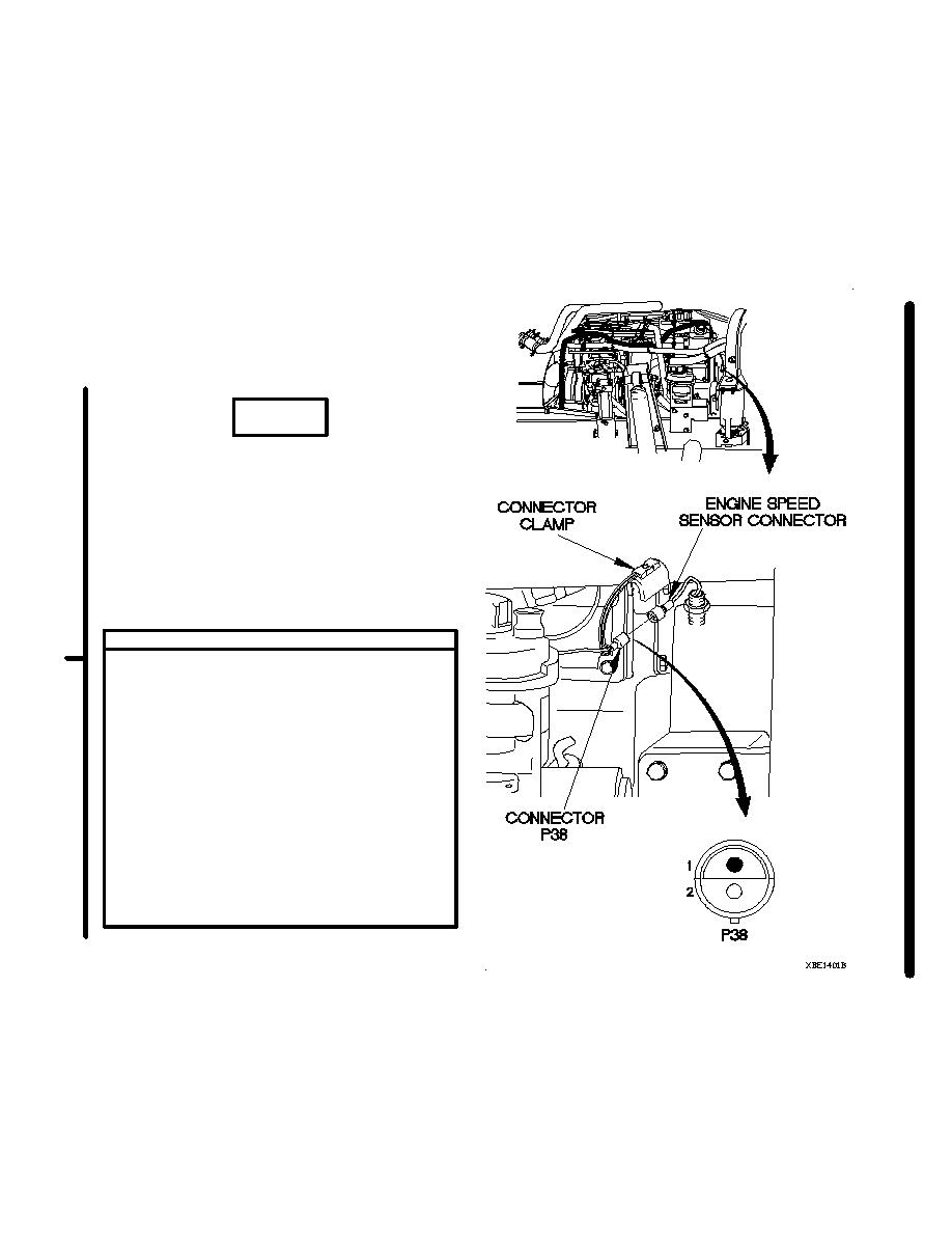
CONTINUITY TEST
(1) Raise cab (TM 9-2320-366-10-1).
(2) Disconnect connector clamp from engine
speed sensor connector.
(3) Disconnect connector P38 from engine
speed sensor connector.
(4) Set multimeter to ohms.
(5) Connect positive (+) probe of multimeter to
socket 1 of engine speed sensor
connector.
(6) Connect negative (-) probe of multimeter to
pin 2 of engine speed sensor connector and
note reading on multimeter.
(7) If greater than 1440 ohms resistance is
present, replace engine speed sensor (para
7-46).
Change 1
2-359
|
|
Privacy Statement - Press Release - Copyright Information. - Contact Us |
