 |
|||
|
|
|||
|
|
|||
| ||||||||||
|
|
 TM 9-2320-366-20-1
CAUTION
Use care when testing electrical connectors.
Do not damage connector pins or sockets
with multimeter probes. Failure to comply
may result in damage to equipment.
NOTE
Inspect connector pins/sockets for damage,
corrosion, and serviceability. Check that
connector pins are not pushed back or not
capable of making good contact.
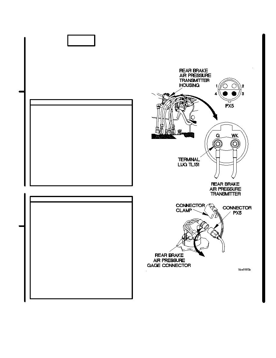
CONTINUITY TEST
NOTE
Remove plastic cable ties as required.
(1) Set multimeter to ohms.
(2) Connect positive (+) probe of multimeter to
connector PX5 pin 4.
(3) Connect negative (-) probe of multimeter to
terminal lug TL151 and note reading on
multimeter.
(4) If continuity is not present, replace wire
1792 from connector PX5 pin 4 to
terminal lug TL151 (para 2-45) or replace
WTEC II dashboard cable assembly
(para 7-10) or WTEC III dashboard cable
assembly (para 7-11).
CONTINUITY TEST
(1) Set multimeter to ohms.
(2) Connect positive (+) probe of multimeter
to rear air brake pressure transmitter
housing.
(3) Connect negative (-) probe of multimeter to
ground and note reading on multimeter.
(4) If continuity is not present, tighten rear
brake air pressure transmitter and fittings
to ensure a good ground.
(5) Connect connector PX5 to REAR BRAKE
AIR pressure gage connector.
(6) Connect connector clamp to REAR BRAKE
AIR pressure gage connector.
NOTE
Install plastic cable ties as required.
(7) Install instrument panel assembly
(para 7-15).
Change 1
2-330.7
|
|
Privacy Statement - Press Release - Copyright Information. - Contact Us |
