 |
|||
|
|
|||
|
|
|||
| ||||||||||
|
|
 TM 9-2320-366-20-1
CAUTION
Use care when testing electrical connectors.
Do not damage connector pins or sockets
with multimeter probes. Failure to comply
may result in damage to equipment.
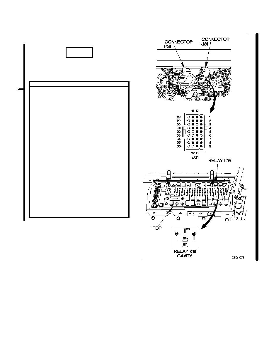
CONTINUITY TEST
(1) Disconnect batteries (para 7-57).
(2) Remove instrument panel for access
(para 7-15).
(3) Disconnect connector J31 from connector
P31.
(4) Set multimeter to ohms.
(5) Connect positive (+) probe of multimeter
to relay K19 socket 87A on PDP.
(6) Connect negative (-) probe of multimeter to
connector J31 pin 14 and note reading on
multimeter.
(7) If continuity is not present, repair wire 54
from connector J31 pin 14 to relay K19
socket 87A on PDP (para 2-45) or replace
WTEC II dashboard cable assembly (7-10)
or WTEC III dashboard cable assembly
(para 7-11).
(8) If continuity is present, repair wire 54 from
connector P31 socket 14 to terminal lug TL
28 (para 2-45) or replace engine control
cable assembly (para 7-80).
(9) Connect connector J31 to connector P31.
(10) Install instrument panel (para 7-15).
(11) Install relay K19 in PDP.
(12) Install PDP cover (para 16-2).
(13) Connect batteries (para 7-57).
Change 1
2-316.3
|
|
Privacy Statement - Press Release - Copyright Information. - Contact Us |
