 |
|||
|
|
|||
|
|
|||
| ||||||||||
|
|
 TM 9-2320-366-20-1
CAUTION
Use care when testing electrical connectors.
Do not damage connector pins or sockets
with multimeter probes. Failure to comply
may result in damage to equipment.
NOTE
Inspect connector pins/sockets for damage,
corrosion, and serviceability. Check that
connector pins are not pushed back or not
capable of making good contact.
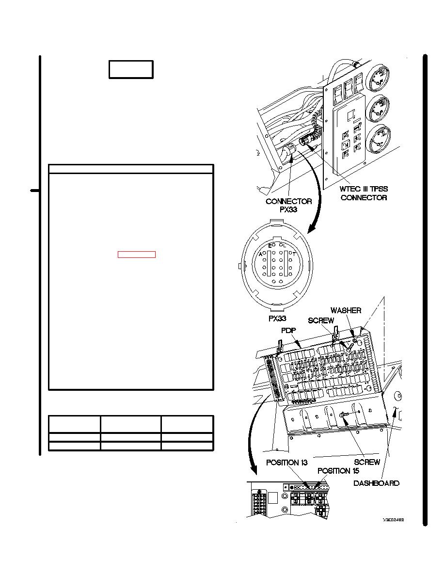
CONTINUITY TEST
(1) Remove instrument panel for access
(para 7-15).
(2) Disconnect connector PX33 from WTEC III
TPSS connector.
(3) Remove three screws and washers from
PDP.
(4) Remove three screws from PDP.
(5) Lift PDP outward to gain access.
(6) Set multimeter to ohms.
(7) For each line of Table 2-8.2. Connector
PX33 Ground Continuity Test perform the
following:
(a) Connect positive (+) probe of
multimeter to connector PX33 socket.
(b) Connect negative (-) probe of
multimeter to terminal board TB2
position and not reading on
multimeter.
(8) If continuity is not present on either wire in
Table 2-8.2. Connector PX33 Ground
Continuity Test repair wire (para 2-45) or
replace WTEC III dashboard cable
assembly (para 7-11).
(9) Install PDP on dashboard with three
screws.
(10) Install three washers and screws in PDP.
Table 2-8.2. Connector PX33 Ground Continuity Test
Connector
Terminal Board
Wire
PX33 Socket
TB2 Position
T
15
186
V
13
188
Change 1
|
|
Privacy Statement - Press Release - Copyright Information. - Contact Us |
