 |
|||
|
|
|||
|
|
|||
| ||||||||||
|
|
 TM 9-2320-366-20-1
CAUTION
Use care when testing electrical connectors.
Do not damage connector pins or sockets
with multimeter probes. Failure to comply
may result in damage to equipment.
NOTE
Inspect connector pins/sockets for damage,
corrosion, and serviceability. Check that
connector pins are not pushed back or not
capable of making good contact.
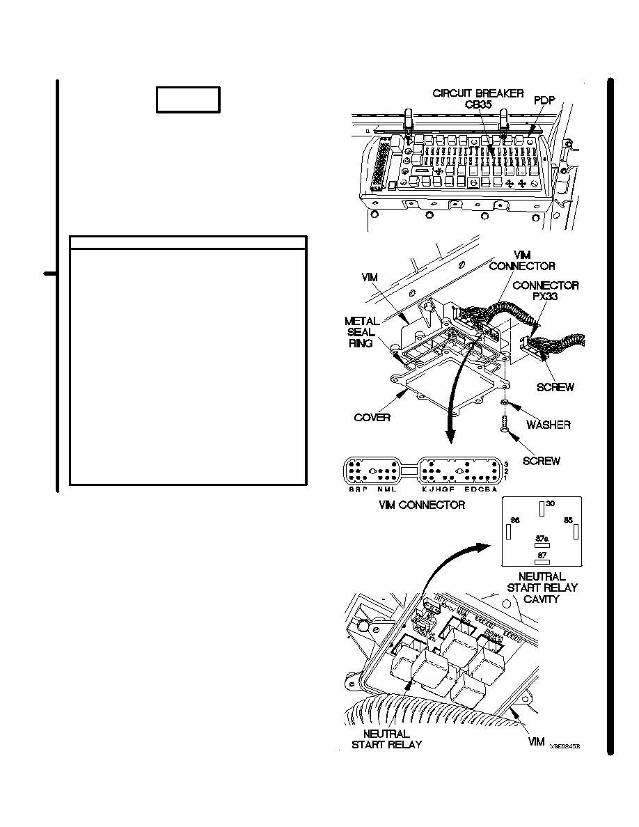
CONTINUITY TEST
(1) Set multimeter to ohms.
(2) Connect positive (+) probe of multimeter
to neutral start relay socket 86 on VIM.
(3) Connect negative (-) probe of multimeter to
VIM connector pin K1 and note reading on
multimeter.
(4) If continuity is not present, replace WTEC II
vehicle interface module (VIM) (para 8-6).
(5) If continuity is present, repair wire 3101
from connector PX33 socket K1 to terminal
board TB2 position 16 on PDP (para 2-45)
or replace WTEC II dashboard cable
assembly (para 7-10).
(6) Install neutral start relay in VIM.
(7) Install cover on VIM with metal seal ring,
eight washers, and screws.
(8) Connect connector PX33 to VIM connector.
(9) Tighten screw in connector PX33.
(10) Install circuit breaker CB35 in PDP.
(11) Install kick panel (para 16-3).
Change 1
2-253
|
|
Privacy Statement - Press Release - Copyright Information. - Contact Us |
