 |
|||
|
|
|||
|
|
|||
| ||||||||||
|
|
 TM 9-2320-366-20-1
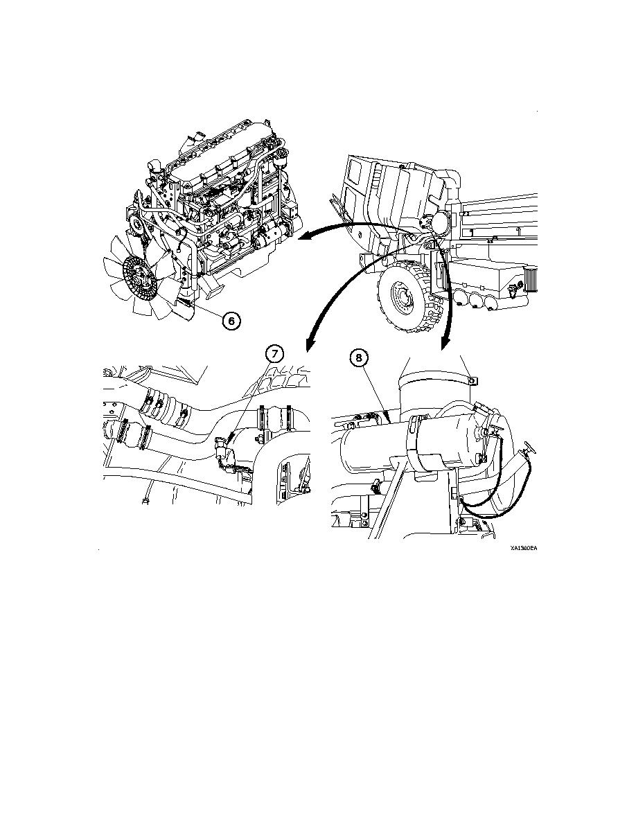
Figure 1-15. Cooling System (Cont)
An engine fan (6) with pneumatic clutch is activated by the water temperature switch (7). When this switch detects a
high temperature condition, air pressure is removed from the fan clutch and the engine fan is engaged. Excess heat
is drawn from the radiator by the flow of air created by the engine fan over the radiator cooling fins. A radiator overflow
tank (8) is provided to allow for expansion of the coolant. The radiator overflow tank also serves as the point where
new coolant is introduced into the cooling system.
1-21
|
|
Privacy Statement - Press Release - Copyright Information. - Contact Us |
