 |
|||
|
|
|||
|
|
|||
| ||||||||||
|
|
 TM 9-2320-279-20-1
Electrical System Maintenance Instructions (Cont)
7-92.
BATTERY BOX AND NATO CONNECTOR REMOVAL/REPAIR/INSTALLATION
(CONT).
NOTE
Support battery box before doing
steps (6) thru (7). M1977-CBT only
has eight holes thru battery box.
Bracket spacers on frame are
used on M984, M1120-LHS and
M1977-CBT. All other models
use flat spacers. On M983 there
are six spacers used.
Do step (6) for all models except
M1120-LHS and M1977-CBT.
Do step (6.1) for M1120-LHS and
M1977-CBT only.
Do step (6.2) for M1120-LHS only.
Do steps (6.3) and (6.4) for
M1977-CBT only.
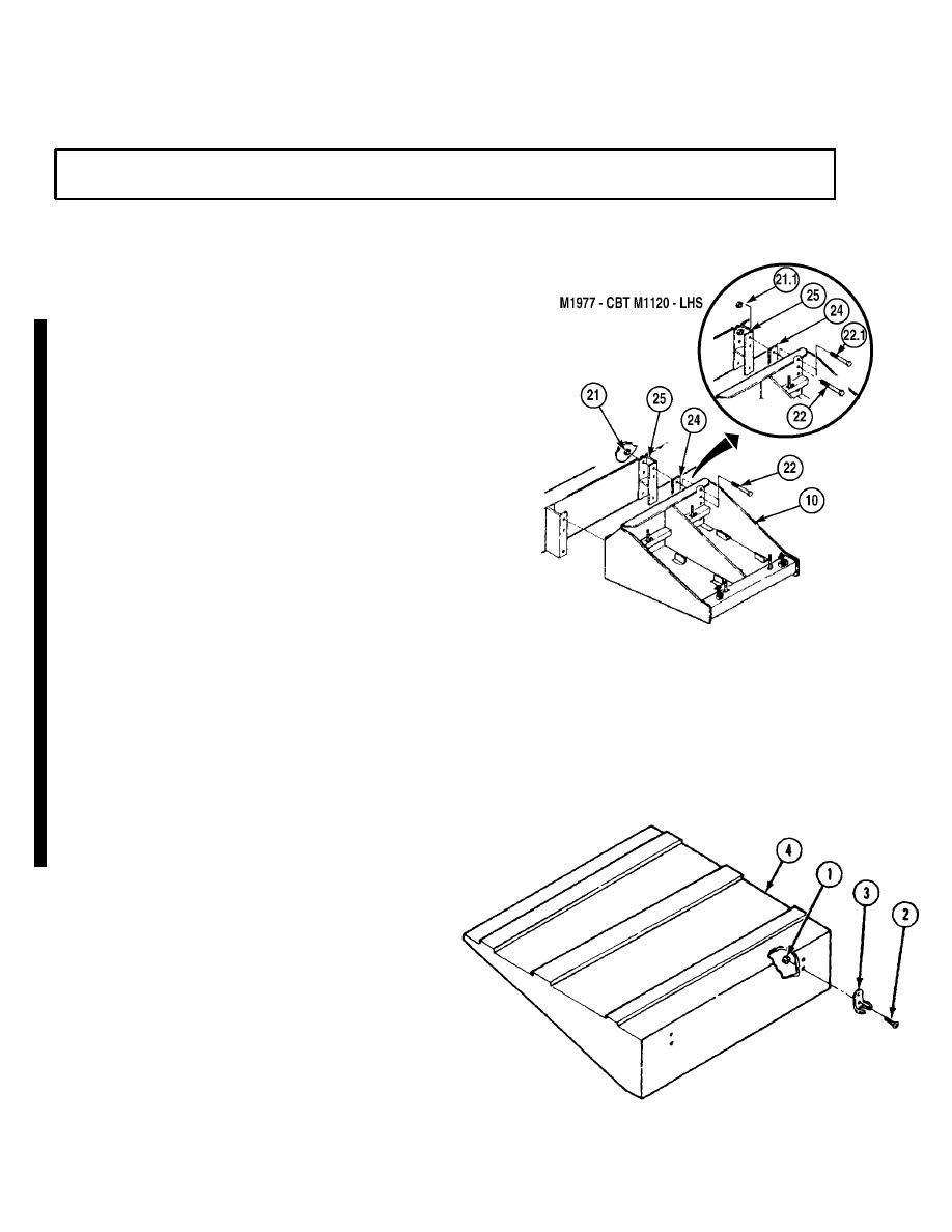
(6)
Soldier A removes six nuts (21), while
Soldier B holds screws (22) in back of
battery box (10).
(6.1)
Soldier A removes one nut (21.1), while
Soldier B holds screw (22.1) in back of
battery box.
(6.2)
Soldier A removes five nuts (21), while
Soldier B holds screws (22) in back of
battery box (10).
(6.3)
Soldier A removes three nuts (21),
while Soldier B holds screws (22) in
back of battery box (10).
(6.4)
Remove three screws (22) and bracket
spacers (25).
(7)
Remove six screws (22) and flat
spacers (24) or bracket spacers (25).
b.
Disassembly.
(1)
Remove four locknuts (1),
screws (2), and two hood
brackets (3) from cover (4).
Change 7
|
|
Privacy Statement - Press Release - Copyright Information. - Contact Us |
