 |
|||
|
|
|||
|
Page Title:
ELECTRIC HORN REMOVAL/INSTALLATION. |
|
||
| ||||||||||
|
|
 TM 9-2320-279-20-1
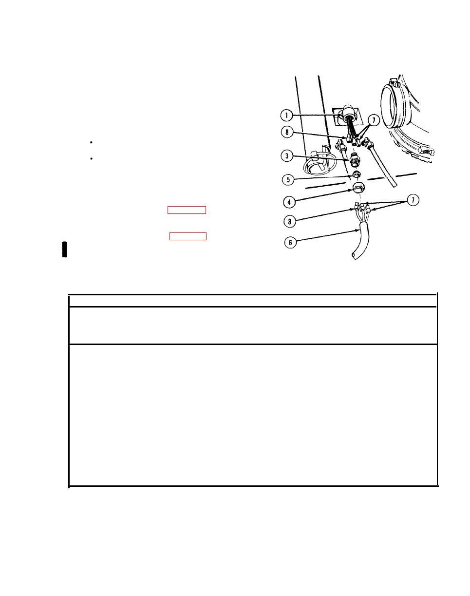
Electrical System Maintenance Instructions (Cont)
(2)
Coat threads of fitting (3) with pipe
thread sealing compound and install
fitting in fuel level sensor (1).
(3)
Install nut (4) and bushing (5) on
line (6).
NOTE
Model A has three connectors.
Model B has two connectors.
(4)
Connect two connectors (7) and
connector (8).
(5)
Install nut (4) on fitting (3).
Follow-on Maintenance.
c.
(1)
Connect batteries (para 7-91).
(2)
Check fuel level sensor for proper
operation and adjust tank level
indicator adjuster (para 7-87).
(3)
Install hose cover (some models only)
(para 16-52.1).
END OF TASK
This task covers:
c. Follow-on Maintenance
a. Removal
b. Installation
INITIAL SETUP
References
Models
None
All
Test Equipment
Equipment Condition
Condition Description
TM or Para
None
TM 9-2320-279-10 Shut off engine.
Skid plate grille
Special Tools
Para 14-5
removed.
None
Special Environmental Conditions
Supplies
None
Tags, identification, Item 48, Appendix C
General Safety Instructions
Personnel Required
None
MOS 63S. Heavy wheel vehicle mechanic
Change 3
|
|
Privacy Statement - Press Release - Copyright Information. - Contact Us |
