 |
|||
|
|
|||
|
|
|||
| ||||||||||
|
|
 TM
9-2320-279-20-1
Electrical System Maintenance Instructions (Cont)
7-87. TANK LEVEL lNDICATOR ADJUSTER REMOVAL/INSTALLATlON/ADJUSTMENT (M978)
(CONT).
a. Removal.
NOTE
There are two kinds of tank level indicator adjusters. Model A has one adjustment screw and is
used only with the plastic fuel level sensor. Model B has four adjustment screws and is used only
with the brass fuel level sensor. If the tank level indicator adjuster must be replaced and one of
the same models is not available, the fuel level sensor must also be replaced. Refer to
TM 9-2320-279-20P for proper parts identification.
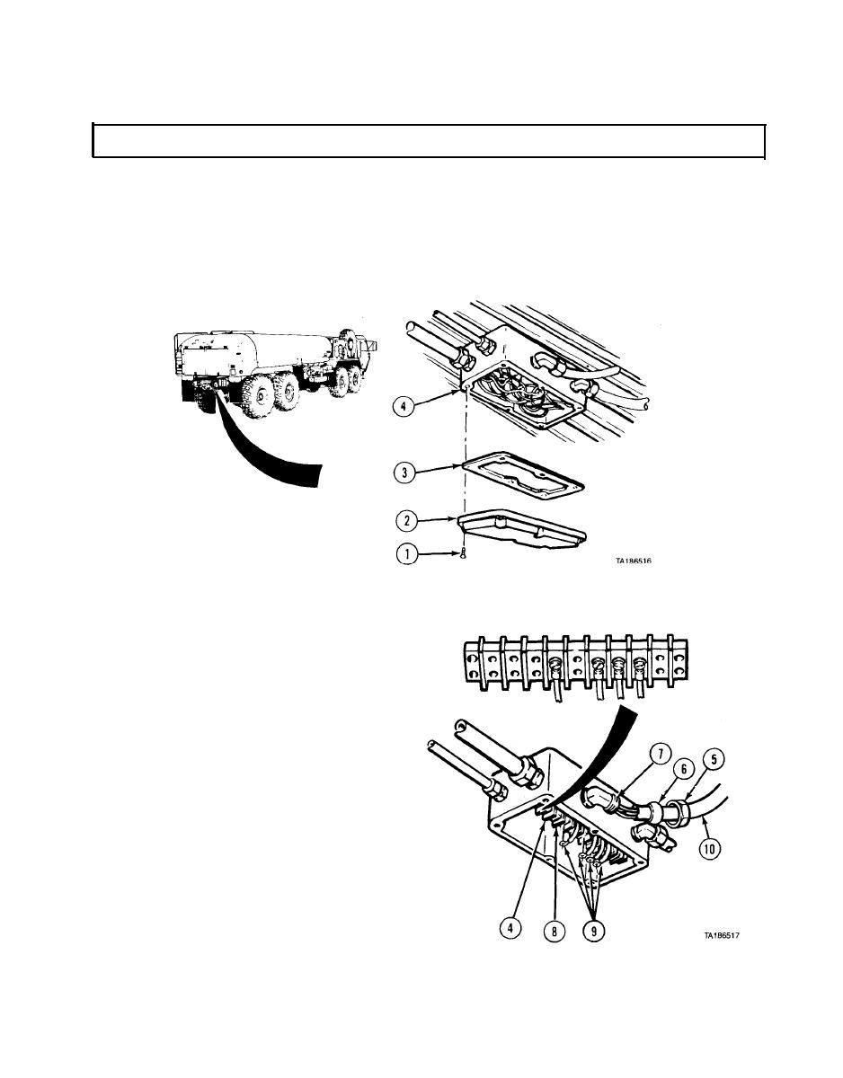
(1) Remove six screws (1), cover (2), and gasket (3) from main junction box (4).
NOTE
Tag and mark all wires before removing.
(2) Loosen nut (5) and compression
fitting (6) from elbow (7).
(3) Loosen four screws (8) and disconnect
four wires (9) from main junction
box (4).
(4) Pull hose (10) and four wires (9) from
main junction box (4).
7-311
|
|
Privacy Statement - Press Release - Copyright Information. - Contact Us |
