 |
|||
|
|
|||
|
Page Title:
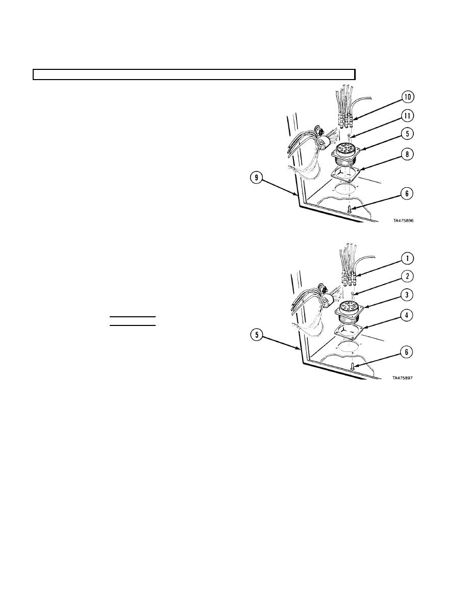
Control Box Connectors Installation. |
|
||
| ||||||||||
|
|
 TM
9-2320-279-20-1
Electrical System Maintenance Instructions (Cont)
7-52.1. CONTROL BOX REMOVAL/REPAIR/INSTALLATION (M984E1) (CONT).
NOTE
Chassis harness connector has 4 plugs. Note
q
position of plugs.
Mark position of connector in control box.
q
Chassis harness connector shown. All
q
connectors similar.
(5) Remove four screws (6), gasket (8), and
connector (5) from control box (9).
(6) Remove wires (10) and plugs (11) from
connector (5).
f. Control Box Connectors Installation.
NOTE
Installation of harness connectors is similar. Winch
q
remote control and chassis harness connectors
are different.
Aline matchmarks on connectors and control box.
q
(1) Install wires (1) and plugs (2) in connector (3).
WARNING
Adhesives, solvents, and sealing compounds can
burn easily, can give off harmful vapors, and are
harmful to skin and clothing. To avoid injury or
death, keep away from open fire and use in
well-ventilated area. If adhesive, solvent, or
sealing compound gets on skin or clothing, wash
immediately with soap and water.
(2) Apply thin coat of adhesive-sealant to connector (3) and gasket (4) and install in control box (5).
(3) Apply corrosion treatment to area where wires (1) enter connector (3).
NOTE
Do step (4) for winch remote control connector. Do step (5) for other connectors.
(4) Install three screws (6) in connector (3).
(5) Install four screws (6) in connector (3).
7-176
|
|
Privacy Statement - Press Release - Copyright Information. - Contact Us |
