 |
|||
|
|
|||
|
|
|||
| ||||||||||
|
|
 TM 9-2320-279-20-1
Electrical System Maintenance Instructions (Cont)
a. Removal
NOTE
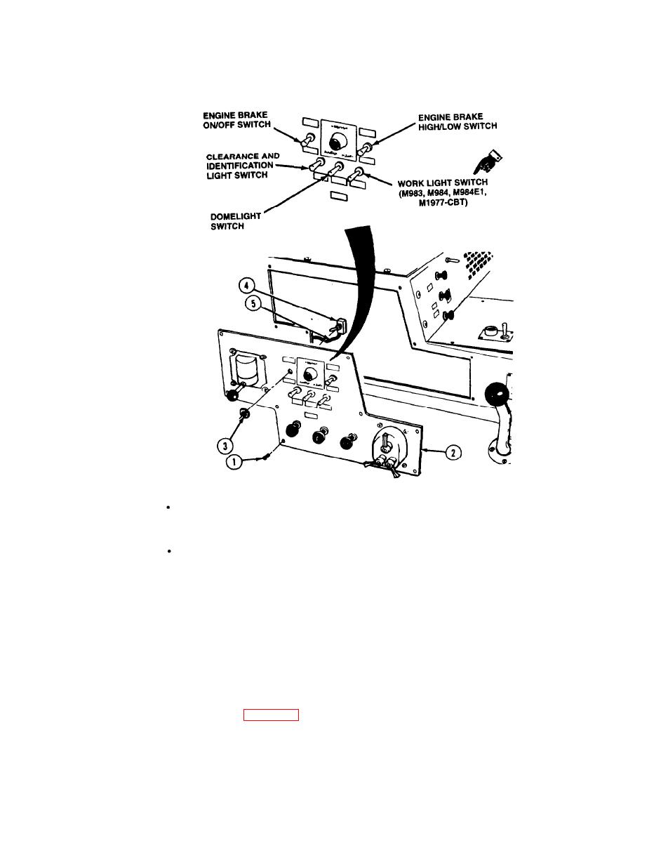
The following switches are removed and installed the same way; ENGINE BRAKE
ON/OFF switch, ENGINE BRAKE HIGH/LOW switch, clearance and identification
light switch, domelight switch, and WORK LIGHT switch.
ENGINE BRAKE ON/OFF switch is shown.
(1) Remove eight screws (1) and side panel (2).
(2) Remove nut (3) and switch (4) from side panel (2).
NOTE
Tag and mark wires before disconnecting.
(3) Disconnect wires (5).
b. Installation.
(1) Connect wires (5) to switch (4).
(2) Install switch (4) and nut (3) on side panel (2). Tighten nut.
(3) position side panel (2) and make sure all wires (5) are behind side panel. Install and tighten
eight screws (1).
Follow-on Maintenance.
C.
(2) Check switch operation (TM 9-2320-279-10).
END OF TASK
7-115
Change 3
|
|
Privacy Statement - Press Release - Copyright Information. - Contact Us |
