 |
|||
|
|
|||
|
|
|||
| ||||||||||
|
|
 TM 9-2320-279-20-1
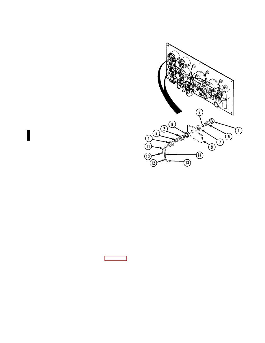
Electrical System Maintenance Instructions (Cont)
a.
Removal.
NOTE
Both warning indicator lights are removed
and installed the same way.
(1)
Pull warning indicator light socket (1)
out of receptacle (2).
(2)
Remove light bulb (3) from warning
indicator light socket (1).
(3)
Remove shield (4). Remove lens (5)
from shield. Remove force ring (6) from
lens.
(4)
Remove nut (7), lockwasher (8), and
receptacle (2) from instrument panel (9).
NOTE
Some trucks do not have butt connectors.
(5)
Cut wire (10) at rear of electrical butt
connector (11).
NOTE
Tag and mark wires before removing.
(6)
Cut wires (12 and 13) at rear of electrical butt
connector (14) and remove warning indicator
light socket (1).
b.
Installation.
(1)
Install lockwasher (8) on receptacle (2) and
insert receptacle through instrument panel (9).
(2)
Install nut (7).
(3)
Install force ring (6) in lens (5). Install lens in shield (4). Install shield.
(4)
Install light bulb (3) in warning indicator light socket (1).
(5)
Install electrical butt connector (11) on wires (10).
(6)
Install electrical butt connector (14) on two wires (12 and 13).
(7)
Install warning indicator light socket (1) in receptacle (2).
c.
Follow-on Maintenance.
(2) Check operation of turn indicator light (TM 9-2320-279-10).
END OF TASK
Change 4
7-99
|
|
Privacy Statement - Press Release - Copyright Information. - Contact Us |
