 |
|||
|
|
|||
|
Page Title:
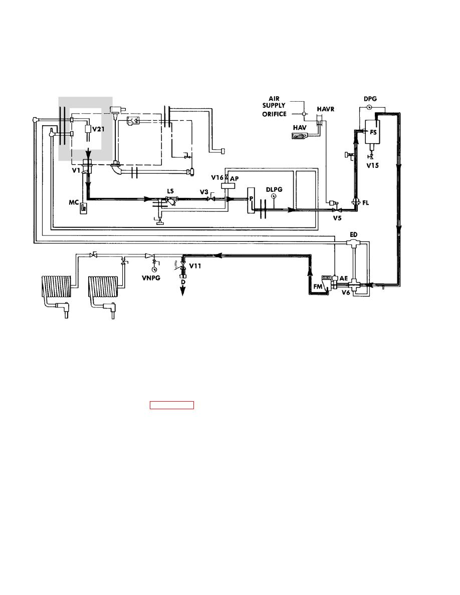
Figure 2-13. Tanker Operation Functional Diagram (Sheet 9 of 12). |
|
||
| ||||||||||
|
|
 TM 9-2320-279-20-1
Troubleshooting Malfunctions (Cont)
Table 2-9. Troubleshooting (Cont)
BULK UNLOAD (FILTERED)
In this operation the tanker's fuel is being pumped out by the vehicle's own pump. Fuel leaves the tank by
valve V1 and flows to the pump. From there it goes through V5 and then to the FS (Filter-Separator). Fil-
tered fuel then flows through valve V6 (Fuel/Defuel Valve) which routes it through the flow meter, V11 flow
regulator valve, and on to receptacle D.
NOTE
Refer to Figure 2-11 for tanker component identification.
Figure 2-13. Tanker Operation Functional Diagram (Sheet 9 of 12).
2-220
Change 4
|
|
Privacy Statement - Press Release - Copyright Information. - Contact Us |
