 |
|||
|
|
|||
|
Page Title:
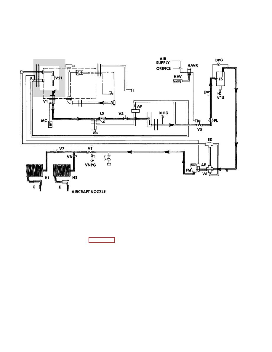
Figure 2-13. Tanker Operation Functional Diagram (Sheet 3 of 12). |
|
||
| ||||||||||
|
|
 TM 9-2320-279-20-1
Troubleshooting Malfunctions (Cont)
Table 2-9. Troubleshooting (Cont)
FUEL SERVICING (AUTOMATIC FILTERED)
Flow leaves the tank through valve V1 and flows to the pump. From there it goes through valve V5 and to
the FS (filter-separator). It then goes to valve V6 where it is routed through the flowmeter and on to either
V7 or V8 depending on which hose reel is selected for use.
NOTE
Refer to Figure 2-11 for tanker component identification.
Figure 2-13. Tanker Operation Functional Diagram (Sheet 3 of 12).
Change 4
|
|
Privacy Statement - Press Release - Copyright Information. - Contact Us |
