 |
|||
|
|
|||
|
|
|||
| ||||||||||
|
|
 TM 9-2320-211-34-2-4
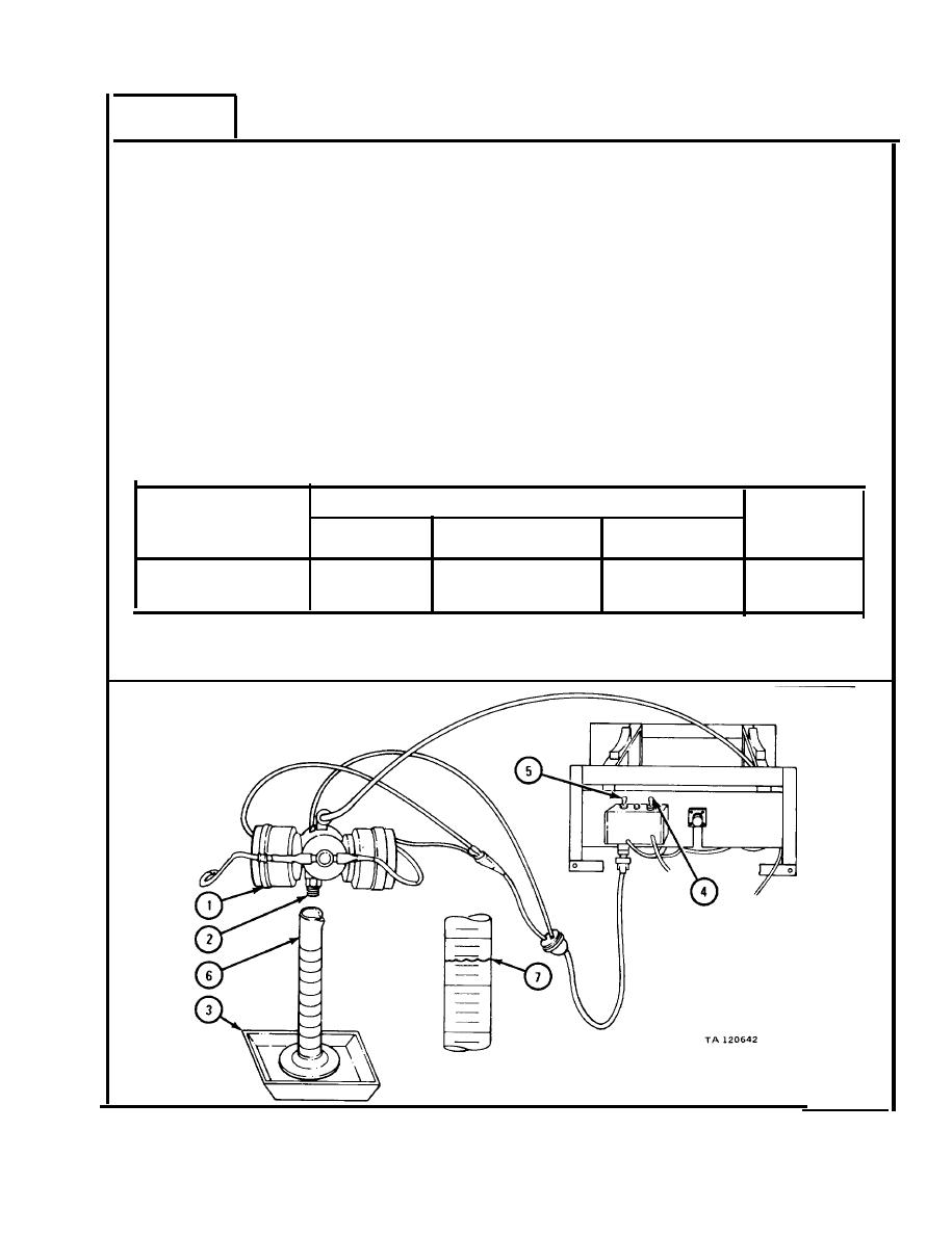
FRAME 4
NOTE
Fuel flow test and adjustment should be done even on
a new fuel control valve. Fuel control valve must be
adjusted for use with different fuels. A stopwatch or
w a t c h with a second hand is needed for this test.
1.
H o l d fuel outlet (1) of fuel control valve (2) over overflow container (3).
2.
B e sure HI-LO switch (4) is in LO position.
F l i p control switch (5) to RUN
p o s i t i o n . F u e l pump should be pumping.
3.
Flip HI-LO switch (4) to HI position. Let fuel flow into overflow container (3)
f o r a few seconds.
4.
L e t fuel flow into graduate (6) for exactly one minute. Flip HI-LO switch (4)
t o LO position. F l i p control switch (5) to OFF position.
5.
P l a c e graduate (6) on a level surface. Read level of fuel (7) as shown. Level
o f fuel should be as in table for type of fuel used.
Diesel Fuel
Combat
F u e l Type
DFA
DF1
DF2
Gasoline
Flow Rate
14 to 18
14 to 18
15 to 19
15 to 19
(cc/mm)
6.
I f fuel flow is not within range of table, get a new fuel control valve (2).
GO TO FRAME 5
19-97
|
|
Privacy Statement - Press Release - Copyright Information. - Contact Us |
