 |
|||
|
|
|||
|
|
|||
| ||||||||||
|
|
 TM 2320-211-34-2-3
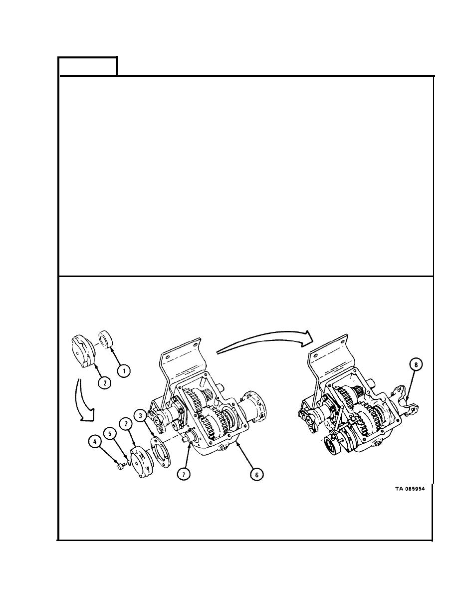
FRAME 9
1.
Press seal (1) into adapter (2).
2.
Put gasket (3) and seal (1) with adapter (2) in place.
3.
Put in four screws (4) and lockwashers (5).
4.
Fasten dial gage to housing (6) so that plunger of dial gage goes through bore in
adapter (2) and rests against pin in end of pump drive shaft (7) as shown.
5.
P u s h in and pull out on coupling (8) to check that end play of pump drive
shaft (7) is between 010 inch and 0.033 inch.
6.
Take off dial gage.
7.
If end play is not within limits given in step 5, do steps 8 through 11. If end play is
within limits given in step 5, go to frame 10.
8.
Take out four screws (4) and lockwashers (5).
9.
T a k e off adapter (2) with seal (1).
10.
Put on another gasket (3). Put adapter (2) with seal (1) back in place.
Do steps 3 through 10 again until end play is within given limits.
11.
GO TO FRAME 10
17-757
|
|
Privacy Statement - Press Release - Copyright Information. - Contact Us |
