 |
|||
|
|
|||
|
|
|||
| ||||||||||
|
|
 TM 9-2320-211-34-2-3
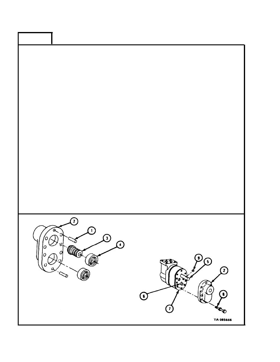
FRAME 3
1.
T a p two pins (1) into front end cover (2).
P r e s s oil seal assembly (3) and two bearings (4) into front end cover (2).
2.
R e f e r to Part 1, para 7-7.
3.
L i n e up bearings (4) in front end cover (2) with drive shaft assembly (5)
and driven shaft assembly (6).
P u s h front end cover (2) with pins (1), oil seal assembly (3), and bearings
4.
( 4 ) into place against hoist pump assembly (7). Notch on front end cover
must be on same side as notches on hoist pump assembly.
5.
C a r e f u l l y clamp hoist pump assembly (7) in vise with soft jaw caps.
6.
P u t in eight screws and lockwashers (8).
T i g h t e n screws (8) to 30 to 40 pound-feet.
7.
T a p key (9) into slot in driveshaft assembly (5).
8.
T a k e hoist pump assembly (7) out of vise.
9.
NOTE
Follow-on Maintenance Action Required:
R e p l a c e hoist pump assembly. Refer to
1.
T M 9-2320-211-20.
2.
R e p l a c e power take off to hydraulic hoist pump.
R e f e r to TM 9-2320-211-20.
3.
F i l l hydraulic reservoir. Refer to
L O 9-2320-211-12.
4.
C h e c k hoist pump assembly for proper operation.
R e f e r to TM 9-2320-211-10.
END OF TASK
17-326
|
|
Privacy Statement - Press Release - Copyright Information. - Contact Us |
