 |
|||
|
|
|||
|
|
|||
| ||||||||||
|
|
 TM 9-2320-211-34-2-2
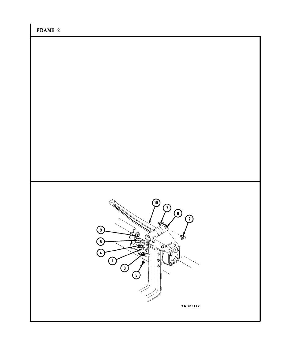
1.
P u t in line and fitting (1).
2.
P u t in lubrication fitting (2).
3.
P u t bracket (3) in place.
P u t in screw (4) and put on nut (5).
4.
P u t in screw (6) and put on nut (7).
5.
Put spring (8) on bracket (9) and brake actuating lever (10).
NOTE
F o l l o w - o n Maintenance Action Required:
1.
R e p l a c e m a s t e r c y l i n d e r . R e f e r to TM 9-2320-211-20.
2.
R e p l a c e clutch actuating lever assembly. Refer to
T M 9-2320-211-20.
3.
R e p l a c e clutch lever return spring. Refer to
T M 9-2320-211-20.
4.
R e p l a c e clutch actuating lever link rod assembly.
R e f e r to TM 9-2320-211-20.
R e p l a c e c l u t c h p e d a l . R e f e r to TM 9-2320-211-20.
5.
6.
R e p l a c e brake pedal. R e f e r to TM 9-2320-211-20.
7.
R e p l a c e cab tunnel. R e f e r to TM 9-2320-211-20.
8.
Replace transfer-to-front axle propeller shaft.
R e f e r to TM 9-2320-211-20.
9.
R e p l a c e left side tool box. R e f e r to TM 9-2320-211-20.
END OF TASK
11-55/(11-56blank)
|
|
Privacy Statement - Press Release - Copyright Information. - Contact Us |
