 |
|||
|
|
|||
|
|
|||
| ||||||||||
|
|
 TM 9-2320-211-34-2-1
FRAME 2
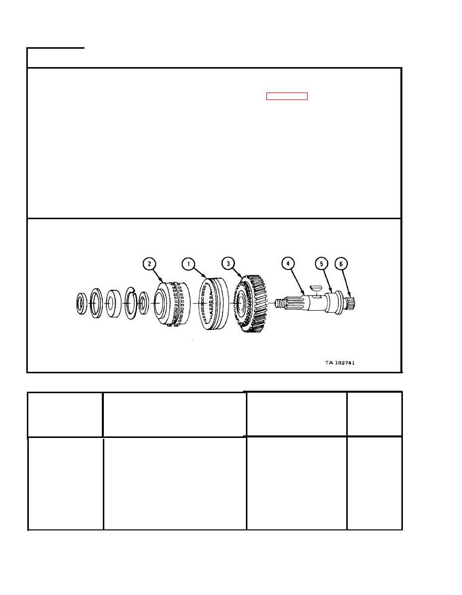
NOTE
R e a d i n g s must be within limits given in table 8-9. If
r e a d i n g s are not within given limits, throw away part
and get a new one.
Measure w i d t h o f g r o o v e s i n s i d e g e a r ( 1 ) .
1.
Measure o u t s i d e diameter of spur gear assembly (2).
2.
Measure i n s i d e diameter of bore in gear (3).
3.
Measure f r o n t output shaft diameter (4).
4.
M e a s u r e f r o n t output shaft diameter (5).
5.
Measure f r o n t output shaft diameter (6).
6.
END OF TASK
NOTE
CHECK ONLY THOSE PARTS WHICH ARE CALLED OUT
PARTS WITHOUT CALLOUTS ARE SHOWN ONLY FOR
REFERENCE PURPOSES.
Front Output Shaft Wear Limits
Size and Fit
Item /Point of Measurement
Index Number
of New Parts
Wear Limit
(inches)
(inches
1
G r o o v e width
0 . 6 0 7 to 0.612
0.618
2
S p u r gear assembly outside
6.6974 to 6.7034
6.6910
diameter
3.001 to 3.002
G e a r bore inside diameter
3.001
3
2.9980
2.9985 to 2.9990
D i a m e t e r of shaft
4
1.8100
1.8103 to 1.8108
D i a m e t e r of shaft
5
2.1652
2.1652 to 2.1657
D i a m e t e r of shaft
6
|
|
Privacy Statement - Press Release - Copyright Information. - Contact Us |
