 |
|||
|
|
|||
|
|
|||
| ||||||||||
|
|
 TM 9-2320-211-20-3-2
1.
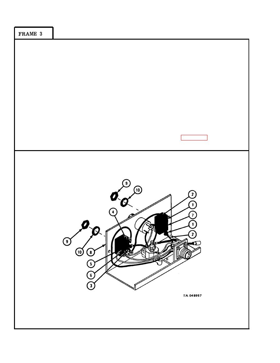
Using screwdriver, screw in and tighten two screws (1) with two wires (2)
as tagged.
2. Put connector jumper (3) and connector (4) on back of heater motor switch (5)
as shown.
3. Using screwdriver, screw in and tighten six screws (6) with six wires as
tagged. Takeoff tags.
4. Put blower switch (7) through hole in control box panel (8) marked HI-LOW.
5. Put heater motor switch (5) through hole in control box panel (8) marked
RUN-OFF-START.
6. Using 9/16-inch wrench, screw on and tighten two nuts (9) with washers (10).
NOTE
Follow-on Maintenance Action Required:
Replace heater control box assembly. Refer to para 21-9.
END OF TASK
21-40
|
|
Privacy Statement - Press Release - Copyright Information. - Contact Us |
