 |
|||
|
|
|||
|
Page Title:
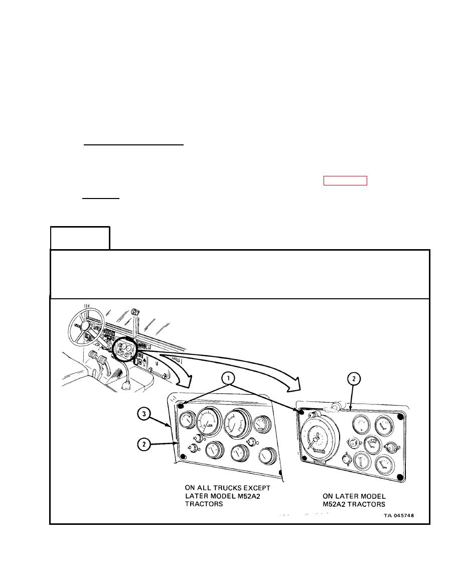
SPEEDOMETER FLEXIBLE SHAFT AND CORE ASSEMBLY REMOVAL AND REPLACEMENT. |
|
||
| ||||||||||
|
|
 TM 9-2320-211-20-3-2
REMOVAL AND REPLACEMENT.
TOOLS: Flat-tip screwdriver
Slip-joint pliers
1/8-inch wrench (2)
3/4-inch wrench
9/16-inch wrench
1-inch wrench
SUPPLIES: None
PERSONNEL: TWO
EQUIPMENT CONDITION: Truck parked, engine off, handbrake set.
a. Preliminary Procedures.
(1) Disconnect battery ground. Refer to Part 1, para 7-44.
(2) Open hood and left side panel. Refer to TM 9-2320-211-10.
(3) Remove front and intermediate tunnels. Refer to para 17-5.
b. Removal.
(1) Flexible shaft assembly.
FRAME 1
1. Using screwdriver, turn four screws (1) 1/4 turn to left.
2. Slide instrument cluster (2) down from instrument panel (3).
GO TO FRAME 2
|
|
Privacy Statement - Press Release - Copyright Information. - Contact Us |
