 |
|||
|
|
|||
|
|
|||
| ||||||||||
|
|
 TM 9-2320-211-20-3-1
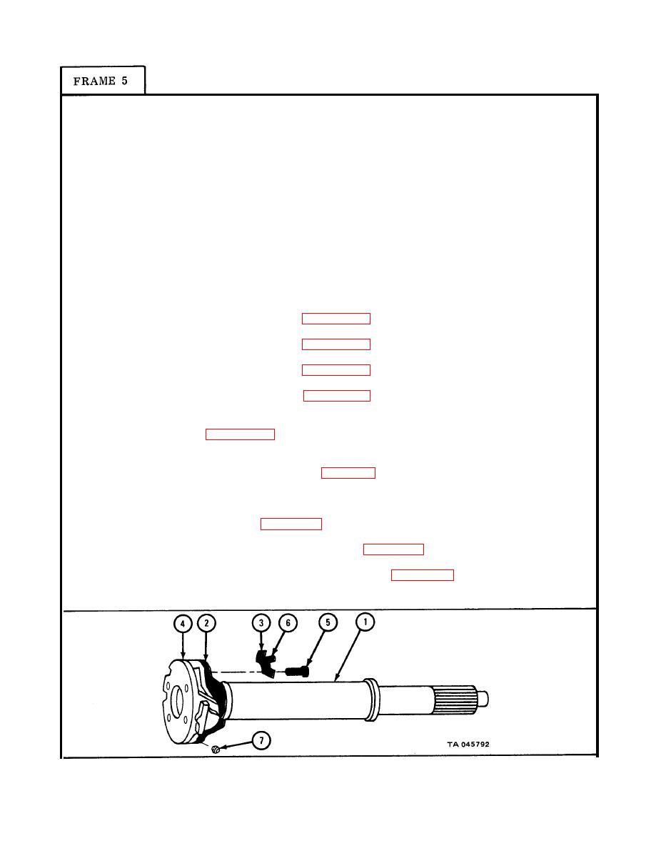
Put propeller shaft (1) in vise and line up holes in yoke (2), holes in two
1.
locking plates (3), and holes in bearings (4).
Push four screws (5) through holes in two locking plates (3).
2.
Using 5/8-inch wrench, screw in and tighten screws (5).
3.
Using 3-inch punch hammer, bend two locking tabs (6) against each screw (5).
4.
Using 9/32-inch wrench, screw in and tighten lubrication fitting (7).
5.
NOTE
Follow-on Maintenance Action Required:
1.
Lubricate universal joint assembly. Refer to
LO 9-2320-211-12.
2.
Replace propeller shaft.
For forward rear axle-to-rear rear axle propeller
a.
shaft, refer to para 10-10.
For power divider-to-bevel gearcase propeller
b.
shaft, refer to para 10-13.
For power divider-to-rear winch propeller
c.
shaft, refer to para 10-12.
For power takeoff-to-front winch propeller
d.
shaft, refer to para 10-11.
e.
For power takeoff-to-hydraulic hoist pump
propeller shaft (truck M51A2) , refer to
f.
For transmission transfer case-to-forward
rear axle (wit h center bearing) (truck
M55A2) , refer to para 10-8.
For transmission transfer case-to-forward
g.
rear axle (without center bearing) (truck
M51A2, M52A2, M54A2, M54A2C, and M543A2),
refer to para 10-7.
h.
For transmission transfer case-to-front axle
propeller shaft, refer to para 10-6.
i.
For transmission-to-transmission transfer
case propeller shaft, refer to para 10-5.
END OF TASK
10-86
|
|
Privacy Statement - Press Release - Copyright Information. - Contact Us |
