 |
|||
|
|
|||
|
|
|||
| ||||||||||
|
|
 TM 9-2320-2S1-20-3-1
FRAME 3
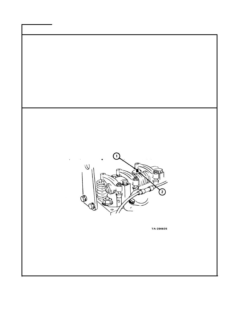
NOTE
Cylinder no. 1 intake valve is now fully open. Intake
valves for cylinder nos. 2, 3, and 6 and exhaust valves
for cylinder nos. 1, 2, and 4 must be set in this position.
Use O. 010-inch feeler gage for intake valves and 0. 025-
inch feeler gage for exhaust valves.
Push feeler gage between rocker arm pad (1) and cylinder no. 2 intake valve
1.
stem (2).
Do step 1 for intake valve nos. 2, 3, and 6 and exhaust valve nos. 1, 2, and
2.
4.
IF
FEELER GAGE FIT IS NOT SNUG FOR ANY VALVE, GO TO FRAME 4.
IF
FEELER GAGE FIT IS SNUG FOR ALL VALVES, GO TO FRAME 5
2-6
|
|
Privacy Statement - Press Release - Copyright Information. - Contact Us |
