 |
|||
|
|
|||
|
|
|||
| ||||||||||
|
|
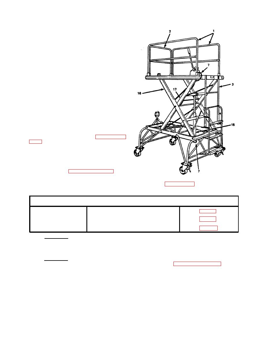 TM55-1730-215-13 & P
(8)
Install cylinder
assembly
by positioning lower
mount on
cylinder (15) to
mounting
bracket on outside
scissors
(16)
(9) Install bolt through
lower mount. Do not tighten bolt
at this time.
(10) Swing cylinder (15)
into position and attach
cylinder ram (upper end) to
inside scissors (17).
(11) Install bolt in upper
end and tighten both bolts as
required.
(12) Connect one end of
hydraulic hose (7) to cylinder
assembly (15).
(13) Attach hose to scissors
assembly (17 and 16) using
five clamps removed in paragraph
3-14a. (2).
(14) Connect hose to
hydraulic pump fitting.
(15) Install upper ladder
(3) and guard rails (1 and 2) as
described in paragraph 3-13a.
(3) and b.(3).
Table 3-9. Main Frame Assembly (Task 3)
TASK No.3
ITEM
Paragraph
Removal
Main Frame Assembly
Inspection
Main Frame Assembly
Main Frame Assembly
Installation
l
a. General. The main frame assembly consists of the main frame plus
a considerable number of attached parts. To remove the main frame for
repair or replacement, almost complete disassembly of the maintenance
platform is required.
b. Removal. To remove the main frame, lower platform and remove the
floor plate and scissors assembly as described in paragraph 3-13 and
Store floor plate, scissors assembly and hydraulic cylinder
3-14.
assembly in a safe place.
|
|
Privacy Statement - Press Release - Copyright Information. - Contact Us |
