 |
|||
|
|
|||
|
|
|||
| ||||||||||
|
|
 TM 5-5420-279-23
(7)
Remove the two setscrews (12) and internal snap ring (11) securing the splined companion
flange (7) to the hydraulic pump drive shaft (10).
(8)
Check all threaded components for wear and damage.
(9)
Check the splines on the splined companion flange (7) for wear and damage.
(10)
Check the condition of the hydraulic hoses and their connections.
(11)
Replace components as necessary.
b.
Install
(1)
Fit the splined companion flange (7) to the hydraulic pump drive shaft (10).
(2)
Fit the internal snap ring (11) to the hydraulic pump drive shaft (10).
(3)
Fit the setscrews (12) hydraulic pump drive shaft (10) and torque tighten to 89 lb/ft
(120 Nm).
(4)
Fit the hydraulic pump (1) to the mounting bracket (2).
(5)
Secure the hydraulic pump (1) with the bolts, washers and new nyloc nuts (8). Torque
tighten to 351 lb/ft (476 Nm).
(6)
Fit the propshaft (5) to the splined companion flange (7).
(7)
Apply thread-locking compound to the bolts (4).
(8)
Secure the propshaft (5) to the splined companion flange (7) with the bolts (4) and torque
tighten to 73 lb/ft (100 Nm).
(9)
Fit the hydraulic hoses to the positions noted during removal.
c.
Follow on tasks
(1)
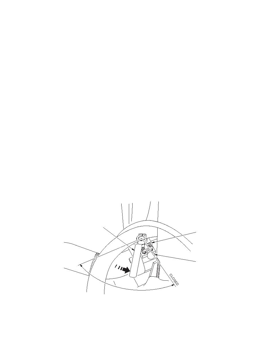
Open the butterfly valve (15).
(2)
Switch the battery shutoff switch to the on position.
(3)
Operate the system and check for leaks.
13
15
EN
14
OP
686A901
6-133
|
|
Privacy Statement - Press Release - Copyright Information. - Contact Us |
