 |
|||
|
|
|||
|
|
|||
| ||||||||||
|
|
 TM 5-5420-279-23
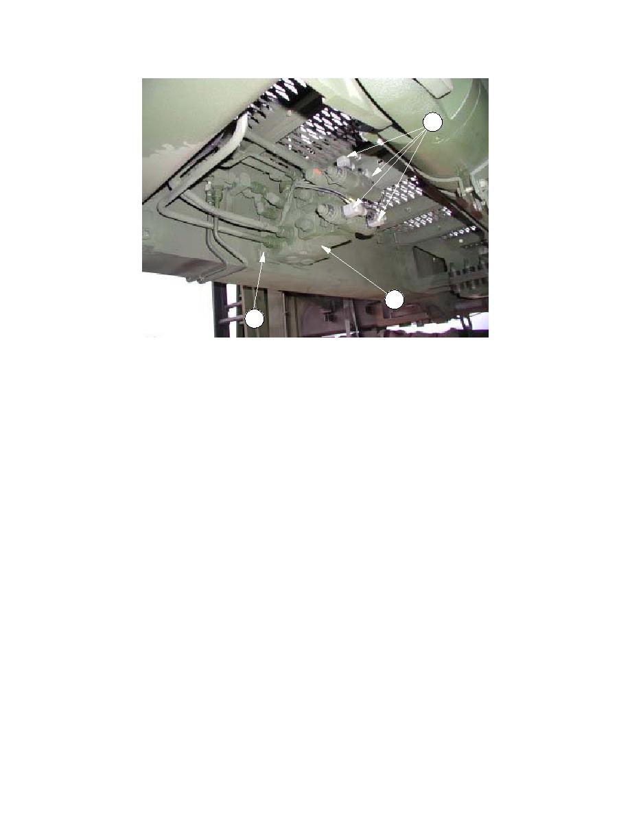
2
1
3
NOTE
The rotate manifold assembly is mounted to the right-hand side of Slide Frame Section 3.
a.
Remove
(1)
De-pressurize the hydraulic system in accordance with unit maintenance procedure 5-118.
(2)
Note the position of and remove hydraulic pipes connected to the rotate manifold assembly
(1).
(3)
Note the position of and remove the electrical connections (2) to the solenoid valves.
(4)
Remove the four bolts and washers (3) mounting the rotate manifold assembly (1) to the
slide frame.
(5)
Remove the rotate manifold (1).
(6)
Examine all threaded components for wear and damage.
(7)
Change components as required.
b.
Install
(1)
Apply thread-locking compound to the mounting bolts.
(2)
Fit the rotate manifold assembly (1) to the sliding frame with the four bolts and washers (3).
(3)
Fit the hydraulic pipes to the positions noted during removal.
(4)
Fit the electrical connections (2) to the positions noted during removal.
c.
Follow on tasks
(1)
Switch the battery shutoff switch to the on position.
(2)
Operate the system and check for correct operation and hydraulic fluid leaks.
6-117
|
|
Privacy Statement - Press Release - Copyright Information. - Contact Us |
