 |
|||
|
|
|||
|
|
|||
| ||||||||||
|
|
 TM 5-5420-279-23
(15)
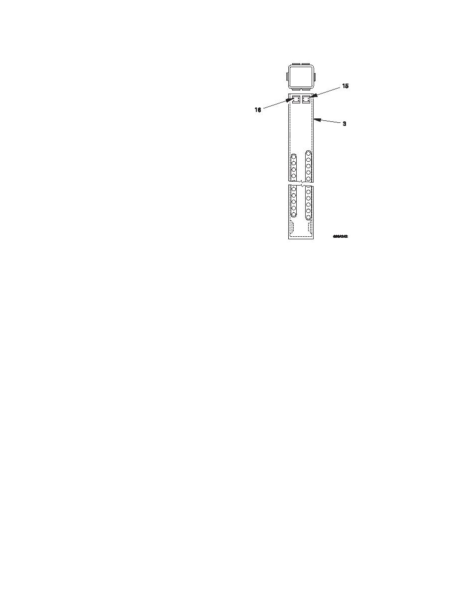
Remove the four screws (15) on each
of the stabilizer leg bearing pads (16)
and remove the bearing pads.
(16)
Measure the bearing pad thickness. If
the bearing pad thickness is 6mm or
less then replace the bearing pads.
(17)
Check the condition of the outer leg
bearing pads and renew if necessary.
(18)
Check all welds for corrosion and
(19)
Check the stabilizer leg locking pin
drillings (17) for wear or damage.
(20)
Check the spacers (5) and (12) from
the cylinder location pins (3) and (13)
for wear or damage.
(21)
Replace components as necessary.
b.
Install
(1)
Install new bearing pads (16) to the stabilizer leg (2) if necessary and secure in position
with screws (15). Use thread-locking compound on the screw threads.
(2)
Insert the stabilizer leg (2) complete with stabilizer leg cylinder into the outer leg section
(14).
(3)
Push the stabilizer leg (2) up through the outer leg section (14) until the mountings for the
outer leg section bearing pads are accessible.
(4)
Install new outer leg section bearing pads as necessary and secure in place with screws,
use locking compound on the threads.
(5)
Extract the stabilizer leg (2) until the top stabilizer cylinder mounting is aligned.
(6)
Insert the cylinder pin (13) and spacers (12).
(7)
Fit and secure the stabilizer cylinder pin boss (11).
(8)
Fit and secure the stabilizer cylinder pin locking plate (9).
(9)
Fit the hydraulic extension unions (7).
(10)
Fit the hydraulic hoses (6) in the positions noted during Remove.
(11)
Operate the stabilizer leg cylinder until the lower cylinder pin location hole is accessible.
(12)
Align the stabilizer leg cylinder with the location pinhole in the stabilizer leg.
(13)
Insert the location pin (3) and fit the spacer (5).
(14)
Fit the snap ring (4) to the location pin (3).
c.
Follow on tasks
(1)
Operate the stabilizer leg in accordance with the operator's manual TM 5-5420-279-10.
(2)
Check for leaks.
|
|
Privacy Statement - Press Release - Copyright Information. - Contact Us |
