 |
|||
|
|
|||
|
|
|||
| ||||||||||
|
|
 TM 5-5420-279-23
(6)
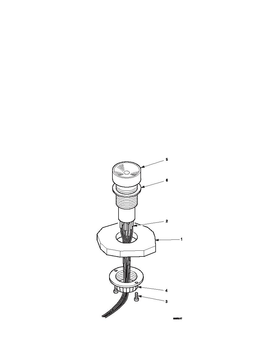
Remove the lock nut (4).
(7)
Remove the control switch (5) complete with seal (6).
b.
Install
(1)
Fit the switch (5) complete with seal (6) to the tail lift pendant body (1).
(2)
Secure the control switch (5) to the tail lift pendant body (1) with the lock nut (4).
(3)
Fit the two lock screws (3).
(4)
Fit a inch piece of heat shrink over the cable ends.
(5)
Solder the cables (2) to the control switch (5) in the positions noted during removal.
(6)
Position the heat shrink protective sleeve over the cable ends (2) and gently apply heat
until the sleeve is protecting the cables.
(7)
Check the tail lift pendant cover seal is clean and not damaged.
(8)
Fit the tail lift cover to the tail lift pendant body (1) with 6 screws and washers. See unit
maintenance procedure 5-155.
c.
Follow on tasks
(1)
Connect the tail lift pendant to the tail lift and check the operation of the tail lift in
accordance with he operator's manual TM 5-5420-279-10.
5-456
|
|
Privacy Statement - Press Release - Copyright Information. - Contact Us |
