 |
|||
|
|
|||
|
Page Title:
Table 1 Cylinder Counterbalance Manifolds |
|
||
| ||||||||||
|
|
 TM 5-5420-279-23
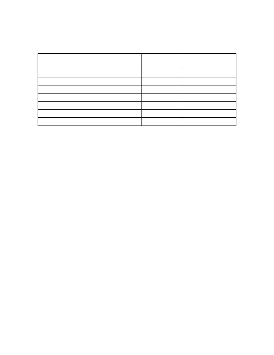
Table 1 Cylinder Counterbalance Manifolds
# OF
# OF
CYLINDER
HYDRAULIC
COUNTERBALANCE
PIPES
VALVES
Raise Cylinder
3
1
Folding Cylinder
3
2
Tilt Roller Cylinder
4
2
Rotate Cylinder
3
1
Stabilizer Cylinder
3
2
Articulator Cylinder
3
1
Stow Cylinder
3
1 (+ 1 pilot valve)
a.
Remove
(1)
De-pressurize the system. Refer to unit maintenance procedure 5-118.
(2)
Release the hydraulic pressure in the cylinder, refer to unit maintenance procedure 5-123.
(3)
Note the positions of and remove the hydraulic pipes (1 and or 3) connected to the
counterbalance manifold (2).
(4)
Remove the screws (5) and lock washers (6) securing the counterbalance manifold (2) to
the cylinder.
(5)
Remove the counterbalance manifold (2) and seal/s (7).
(6)
Remove, if fitted, the counterbalance manifold block (8) and seal/s (7).
(7)
Remove the seal/s (7).
(8)
If required remove the counterbalance valve or pilot vale (4).
b.
Install
(1)
If removed earlier, fit the counterbalance valve or pilot valve (4) to the counterbalance
manifold (2).
(2)
Fit new seal/s (7) to the counterbalance valve (2) and counterbalance valve block (8), if
fitted.
(3)
Fit the counterbalance valve (2) and counterbalance valve block (8) to the cylinder and
secure in place with the new lock washers (6) and screws (5).
(4)
Fit the hydraulic pipes (1 and or 3) to the counterbalance manifold (2).
c.
Follow on task
(1)
Check the operation of the cylinder and check for leaks.
5-409
|
|
Privacy Statement - Press Release - Copyright Information. - Contact Us |
