 |
|||
|
|
|||
|
|
|||
| ||||||||||
|
|
 TM 5-5420-279-23
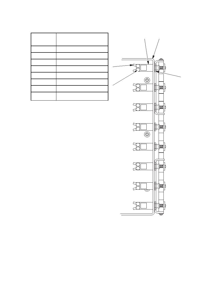
Circuit
Circuit
5
6
Breaker #
1
Main supply
PTO auxiliary
2
3
Controller
9
45A
CB1
4
Launch deployment solenoid
5
Crane
7
6
Tail lift
8
CB2
7.5A
7
Bridge deployment solenoid
PTO main supply
8
a.
Remove
4A
CB3
(1)
Open the cover (2) of the interface
enclosure (1).
(2)
Remove the sixteen screws and
washers (3) securing the operator's
5A
CB4
panel (4) to the interface enclosure
(1).
(3)
Remove to one side, and support, the
operator's panel (4).
20A
CB5
(4)
Remove the cable ties securing the
two harnesses and twelve plugs to the
operator's panel (4).
(5)
Using a suitable marker, mark the
CB6
7.5A
twelve plugs and their positions on the
operator's panel (4).
(6)
Remove the operator's front panel (4).
CB7
15A
(7)
Note the position of and remove the
cables (9) by removing the screws (8).
(8)
Remove the nut and washer (7)
securing the circuit breaker (5) to the
CB8
7.5A
front of the interface enclosure bracket
(6).
686B051
(9)
Remove the circuit breaker (5).
Circuit Breakers
NOTE
The circuit breaker reset button is located on the operator's panel.
5-333
|
|
Privacy Statement - Press Release - Copyright Information. - Contact Us |
